STEERING COLUMN ASSEMBLY REMOVAL

CAUTION:
Some of these service operations affect the SRS airbag system. Read the precautionary notices concerning the SRS airbag system before servicing Click here.
-
POSITION FRONT WHEELS FACING STRAIGHT AHEAD
-
DISCONNECT CABLE FROM NEGATIVE BATTERY TERMINAL
CAUTION:
Wait at least 90 seconds after disconnecting the cable from the negative (-) battery terminal to disable the SRS system.
-
REMOVE FRONT DOOR SCUFF PLATE LH
Tech Tips
Use the same procedure as for the RH side.
-
REMOVE COWL SIDE TRIM BOARD LH
Tech Tips
Use the same procedure as for the RH side.
-
REMOVE FRONT DOOR OPENING TRIM WEATHERSTRIP LH
-
Remove the front door opening trim weatherstrip to the extent necessary to remove the No. 1 lower instrument panel.
-
-
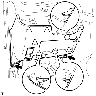
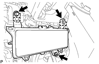
REMOVE LOWER NO. 1 INSTRUMENT PANEL FINISH PANEL
-
Remove the 2 <C> bolts.
-
Disengage the 2 claws and the 7 clips and separate the lower No. 1 instrument panel finish panel.
-
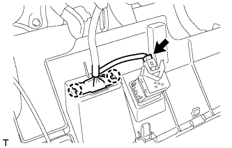
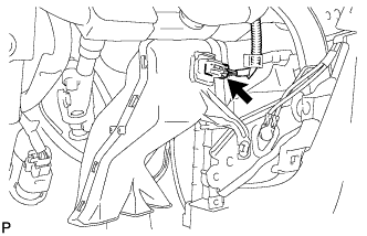
Disconnect the connector.
-
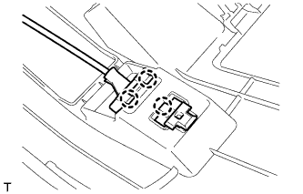
Disengage the 2 claws and disconnect the DLC3 connector.
-
Disengage the 3 claws and disconnect the hood lock control lever.
-
-
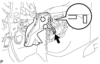
REMOVE KNEE AIRBAG ASSEMBLY
-
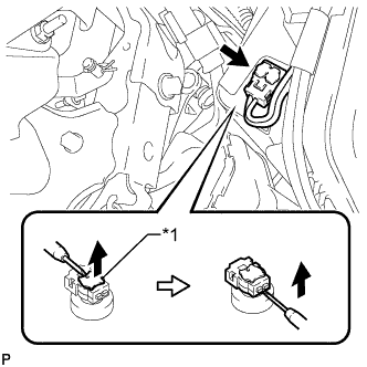
Text in Illustration *1 Locking Button Using a thin-bladed screwdriver, release the locking button.
-
Using a thin-bladed screwdriver, disconnect the airbag connector and remove the instrument panel wire.
-
Remove the 3 bolts.
-
Disengage the 2 guides and remove the knee airbag assembly.
-
-
REMOVE NO. 3 AIR DUCT SUB-ASSEMBLY
-
Disconnect the connector.
Tech Tips
If the vehicle is equipped with stop and start system, disconnect the connector.
-
Remove the clip.
-
Disengage the 3 claws and remove the air duct.
-
-
REMOVE STEERING PAD
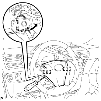
-
Using a thin-bladed screwdriver, push open the spring clips and disengage the pins.
Note
Lightly hold the horn button assembly to prevent it from falling.
-
Pull the steering pad toward you.
-
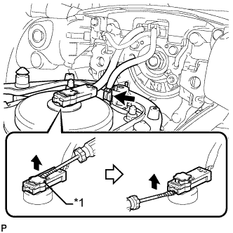
Using a thin-bladed screwdriver, release the locking button.
-
Using a thin-bladed screwdriver, disconnect the connector.
Text in Illustration *1 Locking Button -
Detach the horn terminal.
-
-
REMOVE STEERING WHEEL ASSEMBLY
-
Fully extend and tilt up the steering wheel.
-
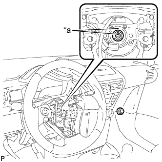
Text in Illustration *a Matchmark Remove the steering wheel assembly set nut.
-
Put matchmarks on the steering wheel assembly and the steering main shaft.
-
Disconnect the connectors from the spiral cable.
-
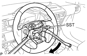
Using SST, remove the steering wheel assembly.
- SST
- 09950-50013 ( 09951-05010, 09952-05010, 09953-05020, 09954-05070 )
Note
Apply a small amount of grease to the threads and tip of SST (center bolt) before use.
-
-
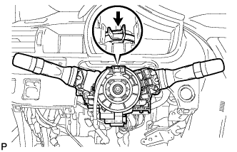
REMOVE STEERING COLUMN COVER SUPPORT (w/ Smart Entry and Start System)
-
Disengage the 4 claws and remove the steering column cover support.
-
-
REMOVE STEERING COLUMN LOWER COVER
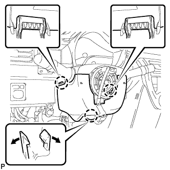
-
Push the right and left sides of the steering column lower cover, and disengage the 2 claws.
-
Insert fingers into the opening of the tilt lever of the steering column lower cover to disengage the claw.
Tech Tips
Spread the claw to disengage it.
-
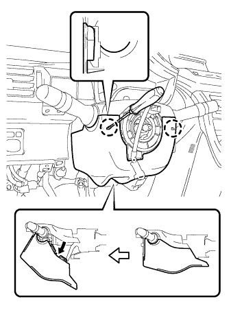
Using a screwdriver, disengage the 2 claws.
-
Turn the steering column lower cover and remove the lower steering column cover as shown in the illustration.
-
-
REMOVE STEERING COLUMN UPPER COVER
-
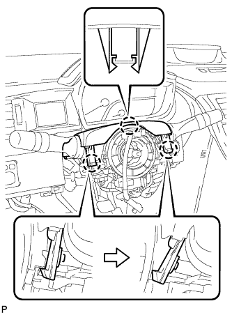
Disengage the 3 claws, and remove the steering column upper cover.
-
-
REMOVE COMBINATION SWITCH ASSEMBLY
-
Disconnect all connectors from the turn signal switch with spiral cable.
-
Use pliers to hold the clamp and raise the claw with a screwdriver. Remove the combination switch assembly together with the spiral cable from the steering column assembly.
-
-
REMOVE NO. 2 STEERING INTERMEDIATE SHAFT ASSEMBLY
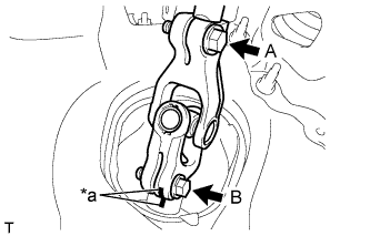
Text in Illustration *a Matchmark
-
Loosen bolt A.
-
Place matchmarks on the No. 2 steering intermediate shaft assembly and steering gear assembly.
-
Remove bolt B and detach the No. 2 steering intermediate assembly from the steering gear assembly.
-
-
REMOVE STEERING COLUMN ASSEMBLY
-
Disconnect all connectors and detach all wire harness clamps from the steering column assembly.
-
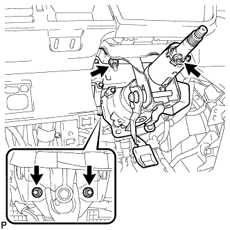
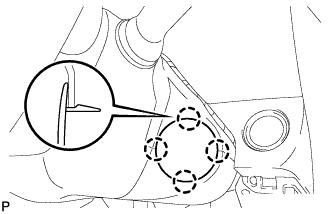
Remove the 4 nuts and remove the steering column assembly from the instrument panel reinforcement assembly.
-