STEERING LOCK SYSTEM, Diagnostic DTC:B2782

| DTC Code | DTC Name |
|---|---|
| B2782 | Power Source Control ECU Malfunction |
DESCRIPTION
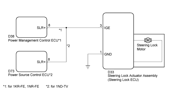
The steering lock ECU activates the steering lock motor by the power from the power management control ECU*1 or power source control ECU*2 through the IGE circuit. This prevents the steering from being locked while the vehicle is moving.
The diagnosis information of the steering lock ECU is transmitted to the tester via the certification ECU because the steering lock ECU is not connected to the CAN communication system.
| DTC No. | DTC Detection Condition | Trouble Area |
|---|---|---|
| B2782 | IGE power supply circuit malfunction |
|
-
*1: for 1KR-FE, 1NR-FE
-
*2: for 1ND-TV
WIRING DIAGRAM
INSPECTION PROCEDURE
Tech Tips
When the engine switch is off, the power management control ECU*1 or power source control ECU*2 may occasionally go into a non-active state called sleep mode. Therefore, before proceeding with the inspection, it is necessary to perform the following step to wake up the ECU.
Connect the intelligent tester to the DLC3 with the engine switch off, and turn any door courtesy switch ON and OFF at 1.5-second intervals until communication between the intelligent tester and the vehicle begins.
-
*1: for 1KR-FE, 1NR-FE
-
*2: for 1ND-TV
PROCEDURE
-
CHECK HARNESS AND CONNECTOR (STEERING LOCK ECU - BODY GROUND)
-
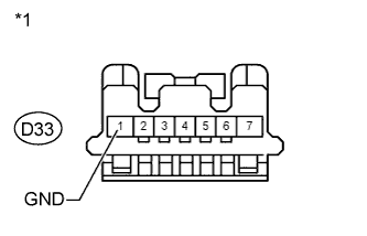
Text in Illustration *1 Front view of wire harness connector:
(to Steering Lock Actuator Assembly (Steering Lock ECU))
Disconnect the connector from the steering lock ECU.
-
Measure the resistance according to the value(s) in the table below.
Standard Resistance Tester Connection Condition Specified Condition D33-1 (GND) - Body ground Always Below 1 Ω
NG 
REPAIR OR REPLACE HARNESS OR CONNECTOR
OK 
-
-
INSPECT STEERING LOCK ACTUATOR ASSEMBLY (STEERING LOCK ECU)
-
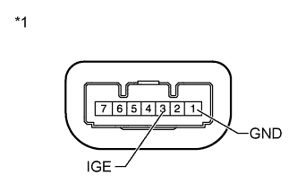
Text in Illustration *1 Component with harness connected:
(Steering Lock Actuator Assembly (Steering Lock ECU))
Reconnect the steering lock ECU connector.
-
Measure the voltage according to the value(s) in the table below.
Standard Voltage Tester Connection Switch Condition Specified Condition D33-3 (IGE) - D33-1 (GND) Engine switch off 11 to 14 V Turn engine switch from off to on (IG) Motor inactive:
11 to 14 V
↓
Motor active:
Below 1 V
↓
Motor inactive:
11 to 14 V
Engine switch on (IG) 11 to 14 V D33-3 (IGE) - D33-1 (GND) Move shift lever to P
↓
Turn engine switch off
↓
Open driver door
Motor inactive:
11 to 14 V
↓
Motor active:
Below 1 V
↓
Motor inactive:
11 to 14 V
Tech Tips
The steering lock ECU and steering lock actuator assembly are supplied as a unit.
NG 
CHECK HARNESS AND CONNECTOR (STEERING LOCK ECU - POWER MANAGEMENT (SOURCE) CONTROL ECU) Click here
OK
-
-
CLEAR DTC
-
Clear DTC Click here.
NEXT
-
-
CHECK DTC OUTPUT
-
Check DTC output Click here.
Result Result Proceed to DTC C2782 is not output A DTC C2782 is output B
B
REPLACE STEERING LOCK ACTUATOR ASSEMBLY (STEERING LOCK ECU) Click here
A 
CHECK INTERMITTENT PROBLEMS Click here
-
-
CHECK HARNESS AND CONNECTOR (STEERING LOCK ECU - POWER MANAGEMENT (SOURCE) CONTROL ECU)
-

Text in Illustration *1 Rear view of wire harness connector:
(to Power Management Control ECU)
*2 Front view of wire harness connector:
(to Steering Lock Actuator Assembly (Steering Lock ECU))
for 1KR-FE, 1NR-FE
-
Disconnect the connector from the steering lock ECU.
-
Disconnect the connector from the power management control ECU.
-
Measure the resistance according to the value(s) in the table below.
Standard Resistance Tester Connection Condition Specified Condition D33-3 (IGE) - D38-8 (SLR+) Always Below 1 Ω D33-3 (IGE) - Body ground Always 10 kΩ or higher
-
-
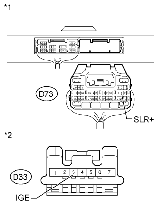
Text in Illustration *1 Rear view of wire harness connector:
(to Power source Control ECU)
*2 Front view of wire harness connector:
(to Steering Lock Actuator Assembly (Steering Lock ECU))
for 1ND-TV
-
Disconnect the connector from the steering lock ECU.
-
Disconnect the connector from the power source control ECU.
-
Measure the resistance according to the value(s) in the table below.
Standard Resistance Tester Connection Condition Specified Condition D33-3 (IGE) - D73-8 (SLR+) Always Below 1 Ω D33-3 (IGE) - Body ground Always 10 kΩ or higher
Result Result Proceed to NG A OK (for 1KR-FE, 1NR-FE) B OK (for 1ND-TV) C -
B
REPLACE POWER MANAGEMENT CONTROL ECU Click here
C
REPLACE POWER SOURCE CONTROL ECU Click here
A
REPAIR OR REPLACE HARNESS OR CONNECTOR
-