STEERING GEAR INSTALLATION

-
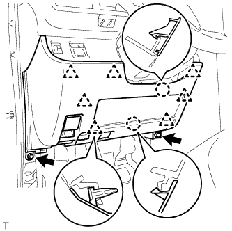
INSTALL STEERING COLUMN HOLE COVER SUB-ASSEMBLY
-
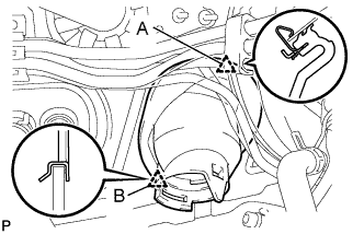
Install clip B onto the body and install the steering column hole cover onto the body by engaging clip A.
-
-
INSTALL STEERING GEAR ASSEMBLY (for LHD)
-
Insert the steering gear assembly into the engine room through the right wheel housing.
Note
-
Do not damage the steering gear rack boot.
-
Do not damage the vehicle body.
-
-
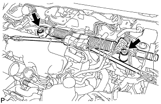
Install the steering gear assembly onto the body with the 2 bolts.
- Torque:
- 87 N*m { 882 kgf*cm, 64 ft.*lbf }
-
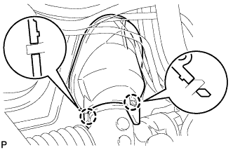
Engage the 2 claws and connect the steering gear assembly to the steering column hole cover sub-assembly.
-
-
INSTALL STEERING GEAR ASSEMBLY (for RHD)
-
Insert the steering gear assembly into the engine room through the left wheel housing.
Note
-
Do not damage the steering gear rack boot.
-
Do not damage the vehicle body.
-
-
Install the steering gear assembly onto the body with the 2 bolts.
- Torque:
- 87 N*m { 882 kgf*cm, 64 ft.*lbf }
-
Engage the 2 claws and connect the steering gear assembly to the steering column hole cover sub-assembly.
-
-
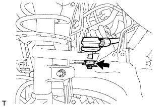
INSTALL TIE ROD END SUB-ASSEMBLY LH
-
Install the tie rod end onto the steering knuckle with a new castle nut.
- Torque:
- 59 N*m { 600 kgf*cm, 43 ft.*lbf }
Note
If the holes for the clip are not aligned, tighten the nut by a further turn of up to 60°.
-
Install a new clip.
-
-
INSTALL TIE ROD END SUB-ASSEMBLY RH
Tech Tips
Use the same procedure for the RH side as for the LH side.
-
INSTALL FRONT WHEEL
- Torque:
- 103 N*m { 1050 kgf*cm, 76 ft.*lbf }
-
INSTALL EXHAUST MANIFOLD W/ TURBOCHARGER (for 1ND-TV)
-
Install the exhaust manifold w/ turbocharger Click here.
-
-
INSTALL INTAKE MANIFOLD SUB-ASSEMBLY (for 1KR-FE, 1NR-FE)
-
for 1KR-FE:
-
Install the intake manifold sub-assembly Click here.
-
-
for 1NR-FE:
-
Install the intake manifold sub-assembly Click here.
-
-
-
INSTALL NO. 2 STEERING INTERMEDIATE SHAFT ASSEMBLY
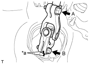
Text in Illustration *a Matchmarks
-
Align the matchmarks and install the No. 2 steering intermediate shaft assembly onto the steering gear sub-assembly.
-
Tighten bolt A.
- Torque:
- 35 N*m { 360 kgf*cm, 26 ft.*lbf }
-
Install the bolt B.
- Torque:
- 35 N*m { 360 kgf*cm, 26 ft.*lbf }
-
-
INSTALL NO. 3 AIR DUCT SUB-ASSEMBLY
-
INSTALL KNEE AIRBAG ASSEMBLY
-
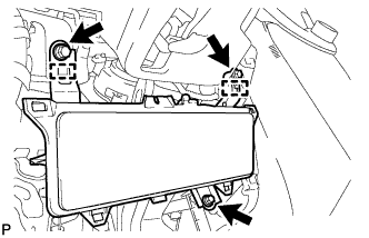
Engage the 2 guides and install the knee airbag assembly.
-
Install the 3 bolts.
- Torque:
- 10 N*m { 102 kgf*cm, 7 ft.*lbf }
-
-
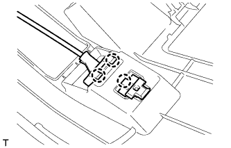
INSTALL LOWER NO. 1 INSTRUMENT PANEL FINISH PANEL
-
Engage the 3 claws and connect the hood lock control lever.
-
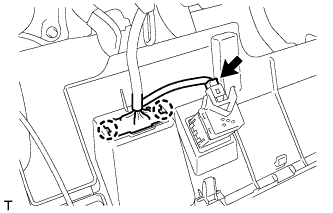
Connect the connector.
-
Engage the 2 claws and connect the DLC3 connector.
-
Engage the 2 claws and 7 clips.
-
Install the lower No. 1 instrument panel finish panel with the 2 <C> bolts.
-
-
INSTALL FRONT DOOR OPENING TRIM WEATHERSTRIP LH
-
INSTALL COWL SIDE TRIM BOARD LH
Tech Tips
Use the same procedure as for the RH side.
-
INSTALL FRONT DOOR SCUFF PLATE LH
Tech Tips
Use the same procedure as for the RH side.
-
CONNECT CABLE FROM NEGATIVE BATTERY TERMINAL
- Torque:
- 5.4 N*m { 55 kgf*cm, 48 in.*lbf }
-
INSPECT SRS WARNING LIGHT
-
POSITION FRONT WHEELS FACING STRAIGHT AHEAD
-
INSPECT FOR EXHAUST GAS LEAK
-
INSPECT AND ADJUST FRONT WHEEL ALIGNMENT