STEERING GEAR REMOVAL

CAUTION:
Some of these service operations affect the SRS airbag system. Read the precautionary notices concerning the SRS airbag system before servicing the steering column Click here.
-
DISCONNECT CABLE FROM NEGATIVE BATTERY TERMINAL
CAUTION:
Wait at least 90 seconds after disconnecting the cable from the negative (-) battery terminal to prevent airbag and seat belt pretensioner activation.
-
POSITION FRONT WHEELS FACING STRAIGHT AHEAD
-
REMOVE FRONT DOOR SCUFF PLATE LH
Tech Tips
Use the same procedure as for the RH side.
-
REMOVE COWL SIDE TRIM BOARD LH
Tech Tips
Use the same procedure as for the RH side.
-
REMOVE FRONT DOOR OPENING TRIM WEATHERSTRIP LH
-
Remove the front door opening trim weatherstrip to the extent necessary to remove the No. 1 lower instrument panel.
-
-
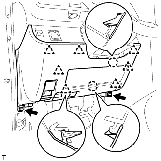
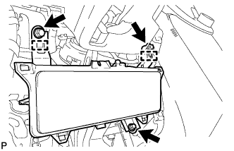
REMOVE LOWER NO. 1 INSTRUMENT PANEL FINISH PANEL
-
Remove the 2 <C> bolts.
-
Disengage the 2 claws and the 7 clips and separate the lower No. 1 instrument panel finish panel.
-
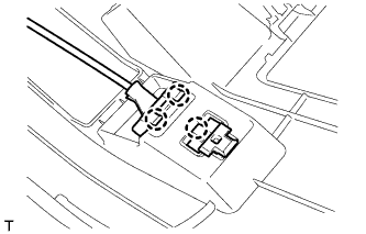
Disconnect the connector.
-
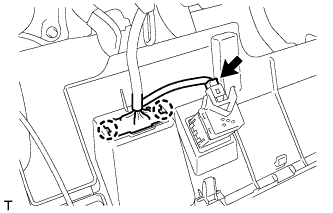
Disengage the 2 claws and disconnect the DLC3 connector.
-
Disengage the 3 claws and disconnect the hood lock control lever.
-
-
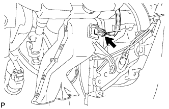
REMOVE KNEE AIRBAG ASSEMBLY
-
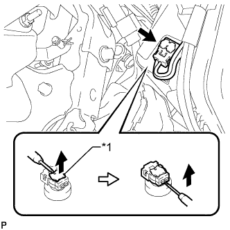
Text in Illustration *1 Locking Button Using a thin-bladed screwdriver, release the locking button.
-
Using a thin-bladed screwdriver, disconnect the airbag connector and remove the instrument panel wire.
-
Remove the 3 bolts.
-
Disengage the 2 guides and remove the knee airbag assembly.
-
-
REMOVE NO. 3 AIR DUCT SUB-ASSEMBLY
-
Disconnect the connector.
Tech Tips
If the vehicle is equipped with stop and start system, disconnect the connector.
-
Remove the clip.
-
Disengage the 3 claws and remove the air duct.
-
-
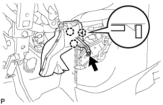
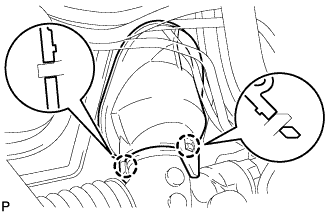
SEPARATE NO. 2 STEERING INTERMEDIATE SHAFT ASSEMBLY
-
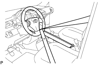
Use a seat belt to fix the steering wheel assembly in place, in order to avoid breaking of the spiral cable.
-
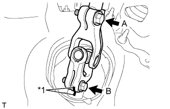
Text in Illustration *1 Matchmark Place matchmarks on the intermediate shaft and the steering gear sub-assembly.
-
Loosen bolt A, remove bolt B and separate the No. 2 steering intermediate shaft assembly.
-
-
SEPARATE STEERING COLUMN HOLE COVER SUB-ASSEMBLY
-
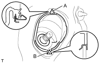
Disengage clip A, separate clip B from the body and separate the steering column hole cover sub-assembly.
-
-
REMOVE FRONT WHEEL
-
REMOVE INTAKE MANIFOLD SUB-ASSEMBLY (for 1KR-FE, 1NR-FE)
-
for 1KR-FE:
-
Remove the intake manifold sub-assembly Click here.
-
-
for 1NR-FE:
-
Remove the intake manifold sub-assembly Click here.
-
-
-
REMOVE EXHAUST MANIFOLD W/ TURBOCHARGER (for 1ND-TV)
-
Remove the exhaust manifold w/ turbocharger Click here.
-
-
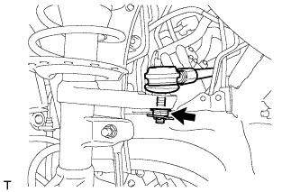
SEPARATE TIE ROD END SUB-ASSEMBLY LH
-
Remove the cotter pin and castle nut.
-
Install SST (spacer B) to the threaded section of the tie rod end.
- SST
- 09960-20010 ( 09961-02060 )
Note
Make sure the upper ends of the threaded section of the tie rod end and SST (spacer B) are aligned.
-
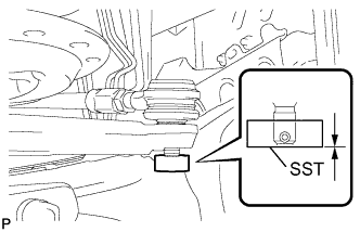
Using SST, separate the tie rod end from the front axle assembly.
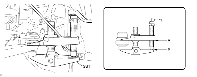
Text in Illustration *1 Place the wrench here - SST
- 09960-20010 ( 09961-02010 )
Note
-
Make sure to tie the string of SST to the vehicle to prevent SST from dropping.
-
Install SST so that A and B are parallel.
-
Be sure to place the wrench on the part indicated in the illustration.
-
Do not damage the ball joint dust cover.
-
Do not damage the front disc brake dust cover.
-
-
SEPARATE TIE ROD END SUB-ASSEMBLY RH
Tech Tips
Use the same procedure for the RH side as for the LH side.
-
REMOVE STEERING GEAR ASSEMBLY (for LHD)
-
Disengage the 2 claws and separate the steering gear.
-
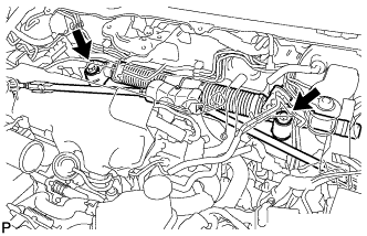
Remove the 2 bolts and the steering gear assembly from the body.
-
Remove the steering gear assembly through the right wheel housing.
Note
-
Do not damage the steering gear rack boot.
-
Do not damage the vehicle body.
-
-
-
REMOVE STEERING GEAR ASSEMBLY (for RHD)
-
Remove the 2 bolts and the power steering gear from the body.
-
Remove the steering gear assembly through the left wheel housing.
Note
-
Do not damage the steering gear rack boot.
-
Do not damage the vehicle body.
-
-