PARKING BRAKE CABLE (for Rear Disc Brake) INSTALLATION

-
INSTALL NO. 2 PARKING BRAKE CABLE ASSEMBLY
-
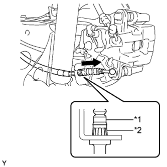
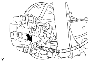
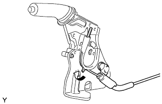
Text in Illustration *1 No. 2 Parking Brake Cable Assembly *2 Clip Insert the parking brake cable into the disc brake cylinder and engage the clip claws of the parking brake cable to the rear disc brake cylinder guide as shown in the illustration.
-
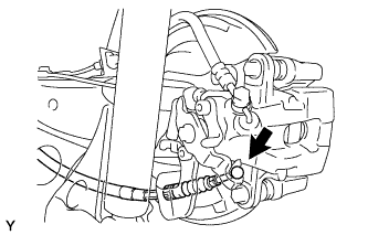
Connect the cable end to the rear disc brake cylinder operation lever.
-
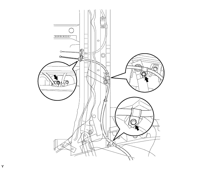
Install the No. 2 parking brake cable assembly with the 3 bolts.
- Torque:
- 6.0 N*m { 61 kgf*cm, 53 in.*lbf }
-
-
INSTALL NO. 3 PARKING BRAKE CABLE ASSEMBLY
-
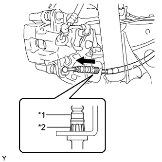
Text in Illustration *1 No. 3 Parking Brake Cable Assembly *2 Clip Insert the parking brake cable into the disc brake cylinder and engage the clip claws of the parking brake cable to the rear disc brake cylinder guide as shown in the illustration.
-
Connect the cable end to the rear disc brake cylinder operation lever.
-
Install the No. 3 parking brake cable assembly with the 3 bolts.
- Torque:
- 6.0 N*m { 61 kgf*cm, 53 in.*lbf }
-
-
INSTALL REAR WHEELS
- Torque:
- 103 N*m { 1050 kgf*cm, 76 ft.*lbf }
-
INSTALL NO. 1 PARKING BRAKE CABLE ASSEMBLY
-
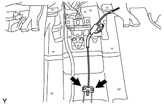
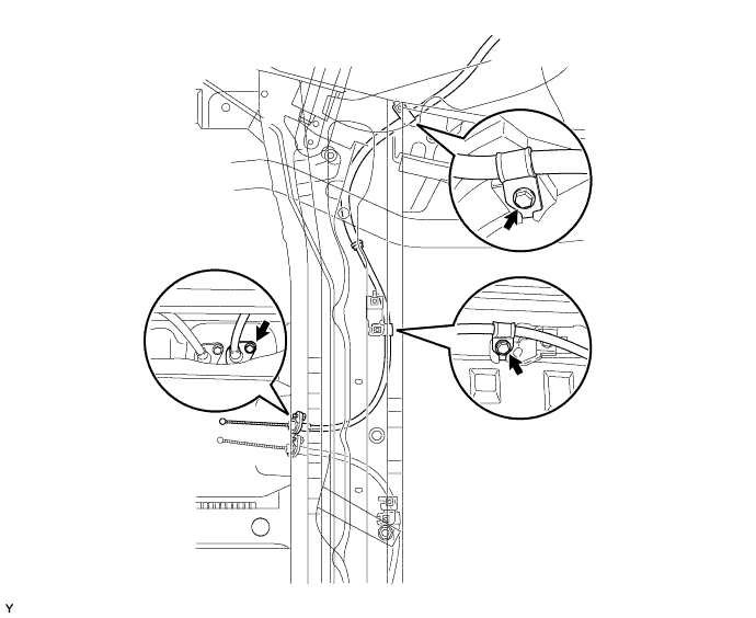
Connect the cable ends of the No. 2 and No. 3 parking cable assemblies to the No. 1 parking cable assembly.
-
-
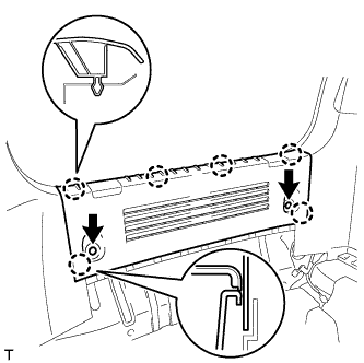
INSTALL PARKING BRAKE CABLE COVER
-
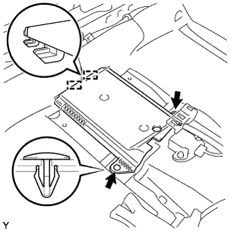
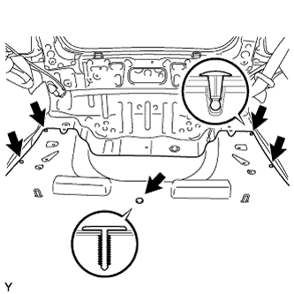
Insert the 2 guides.
-
Using the 2 clips, install the parking brake cable cover.
-
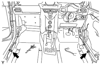
Engage the 2 hooks of the floor carpet and place the floor carpet in its original position.
-
Install the floor carpet with the 5 clips.
-
-
INSTALL PARKING BRAKE LEVER SUB-ASSEMBLY
-
Pass the No. 1 parking brake cable assembly through the parking brake lever sub-assembly.
-
Bend the parking brake lever claw.
-
Install the parking brake lever sub-assembly with the 2 bolts.
- Torque:
- 15 N*m { 148 kgf*cm, 11 ft.*lbf }
-
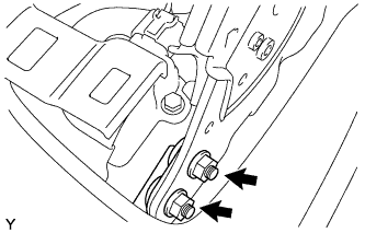
Tighten the 2 nuts.
- Torque:
- 17 N*m { 173 kgf*cm, 13 ft.*lbf }
-
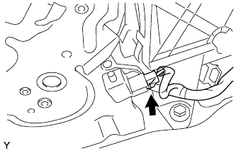
Connect the parking brake switch connector.
-
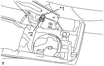
Text in Illustration *1 Lock Nut *2 Adjusting Nut Temporarily install the adjusting nut and the lock nut to the No. 1 parking brake cable assembly.
-
-
ADJUST PARKING BRAKE TRAVEL
-
Completely release the parking brake lever.
-
Text in Illustration *1 Lock Nut *2 Adjusting Nut Loosen the lock nut and the adjusting nut to completely release the parking brake cable.
-
Fully depress the brake pedal 3 to 5 times with the engine stopped.
-
Turn the adjusting nut until the parking brake lever travel is corrected to within the specified range.
Parking brake lever travel at 200 N (20 kgf, 45.0 lbf) Rear Brake Type Number of Clicks Disc 5 to 8 Drum 6 to 9 -
Using a wrench or an equivalent tool, hold the adjusting nut and tighten the lock nut.
- Torque:
- 6.0 N*m { 61 kgf*cm, 53 in.*lbf }
-
Operate the parking brake lever 3 to 4 times, and check the parking brake lever travel.
-
Check whether the parking brake drags or not.
-
-
INSPECT REAR DISC BRAKE CYLINDER OPERATION LEVER AND STOPPER CLEARANCE
-
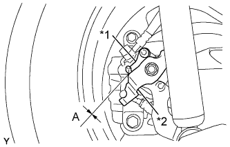
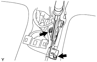
Text in Illustration *1 Stopper *2 Operation Lever Release the parking brake lever and check that the clearance measurement between the rear disc brake cylinder operation lever and the stopper is within the specified range.
Clearance A 0.5 mm (0.0197 in.) or less If the clearance is not within the specified range, replace the rear disc brake caliper assembly.
-
-
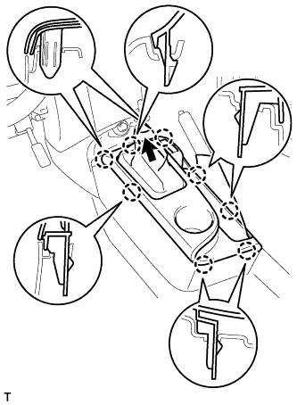
INSTALL REAR CONSOLE BOX ASSEMBLY

-
Engage the 2 front clips.
-
Rotate the 2 rear clips in the direction indicated by the arrows to engage them and install the console box assembly RR.
-
-
INSTALL CONSOLE UPPER PANEL SUB-ASSEMBLY (for Manual Transaxle)
-
Install the shifting hole cover onto the shift lever.
-
Engage the 8 claws and install the console upper panel.
-
-
INSTALL CONSOLE UPPER PANEL SUB-ASSEMBLY (for CVT)
-
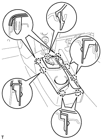
Engage the 8 claws and install the console upper panel.
-
-
INSTALL SHIFT LEVER KNOB SUB-ASSEMBLY (for Manual Transaxle)
-
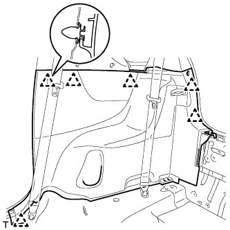
INSTALL SIDE NO. 1 TRIM ASSEMBLY RH
-
Engage the 6 clips and install the side No. 1 trim.
-
-
INSTALL SIDE NO. 1 TRIM ASSEMBLY LH
Tech Tips
Use the same procedure as for the RH side.
-
INSTALL DECK TRIM SIDE BELT HOLE COVER RH
-
Engage the 5 claws and install the deck trim side belt hole cover.
-
-
INSTALL DECK TRIM SIDE BELT HOLE COVER LH
Tech Tips
Use the same procedure as for the RH side.
-
INSTALL BACK DOOR WEATHERSTRIP
-
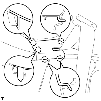
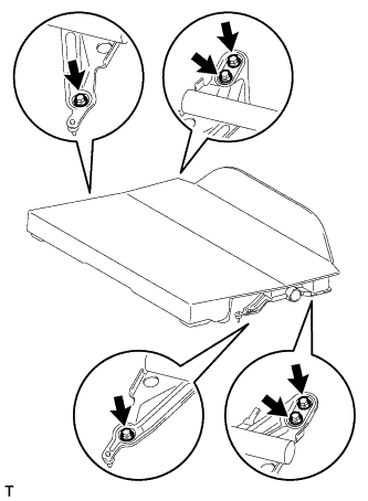
INSTALL REAR DECK TRIM COVER
-
Engage the 6 claws.
-
Install the rear deck trim cover with the 2 clips.
-
-
INSTALL FRONT DOOR OPENING TRIM WEATHERSTRIP RH
-
INSTALL FRONT DOOR OPENING TRIM WEATHERSTRIP LH
-
INSTALL FRONT DOOR SCUFF PLATE RH
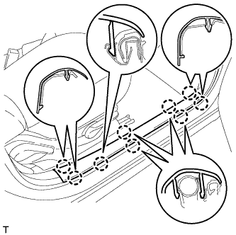
-
Engage the 9 claws and install the front door scuff plate.
-
-
INSTALL FRONT DOOR SCUFF PLATE LH
Tech Tips
Use the same procedure as for the RH side.
-
INSTALL LUGGAGE COMPARTMENT TRAY
-
INSTALL REAR SEAT SUB FLOOR BOARD ASSEMBLY (w/o Rear Seat Assembly)
-
Install the rear floor board with the 6 bolts.
- Torque:
- 37 N*m { 377 kgf*cm, 27 ft.*lbf }
-
-
INSTALL REAR SEAT UNDER TRAY
-
INSTALL REAR SEAT ASSEMBLY (w/ Rear Seat Assembly)
-
Install the rear seat assembly Click here.
-
-
INSTALL FRONT SEAT ASSEMBLY
-
Install the front seat assembly Click here.
-