PARKING BRAKE LEVER INSTALLATION

-
INSTALL PARKING BRAKE SWITCH ASSEMBLY
-
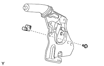
Install the parking brake switch assembly to the parking brake lever assembly with the screw.
- Torque:
- 0.9 N*m { 9 kgf*cm, 8 in.*lbf }
-
-
INSTALL PARKING BRAKE LEVER SUB-ASSEMBLY
-
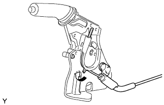
Pass the No. 1 parking brake cable assembly through the parking brake lever sub-assembly.
-
Bend the parking brake lever claw.
-
Install the parking brake lever sub-assembly with the 2 bolts.
- Torque:
- 15 N*m { 148 kgf*cm, 11 ft.*lbf }
-
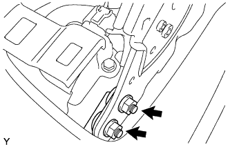
Tighten the 2 nuts.
- Torque:
- 17 N*m { 173 kgf*cm, 13 ft.*lbf }
-
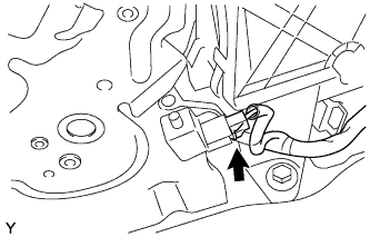
Connect the parking brake switch connector.
-
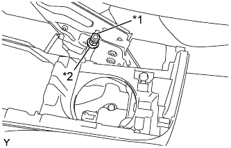
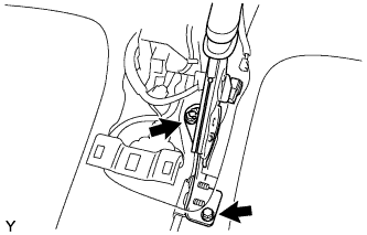
Text in Illustration *1 Lock Nut *2 Adjusting Nut Temporarily install the adjusting nut and the lock nut to the No. 1 parking brake cable assembly.
-
-
ADJUST PARKING BRAKE LEVER TRAVEL
-
Completely release the parking brake lever.
-
Text in Illustration *1 Lock Nut *2 Adjusting Nut Loosen the lock nut and the adjusting nut to completely release the parking brake cable.
-
Fully depress the brake pedal 3 to 5 times with the engine stopped.
-
Turn the adjusting nut until the parking brake lever travel is corrected to within the specified range.
Parking brake lever travel at 200 N (20 kgf, 45.0 lbf) Rear Brake Type Number of Clicks Disc 5 to 8 Drum 6 to 9 -
Using a wrench or an equivalent tool, hold the adjusting nut and tighten the lock nut.
- Torque:
- 6.0 N*m { 61 kgf*cm, 53 in.*lbf }
-
Operate the parking brake lever 3 to 4 times, and check the parking brake lever travel.
-
Check whether the parking brake drags or not.
-
-
INSPECT BRAKE WARNING LIGHT
-
When operating the parking brake lever, check that the brake warning light illuminates.
OK The brake warning light always illuminates at the first click.
-
-
INSTALL CONSOLE UPPER PANEL SUB-ASSEMBLY (for Manual Transaxle)
-
Install the shifting hole cover onto the shift lever.
-
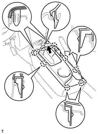
Engage the 8 claws and install the console upper panel.
-
-
INSTALL CONSOLE UPPER PANEL SUB-ASSEMBLY (for CVT)
-
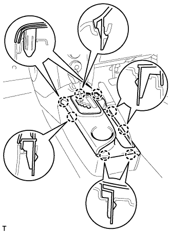
Engage the 8 claws and install the console upper panel.
-
-
INSTALL SHIFT LEVER KNOB SUB-ASSEMBLY (for Manual Transaxle)