REAR BRAKE (for Drum Type) INSTALLATION

-
INSTALL REAR BRAKE DRUM
-
ADJUST REAR DRUM BRAKE SHOE CLEARANCE
-
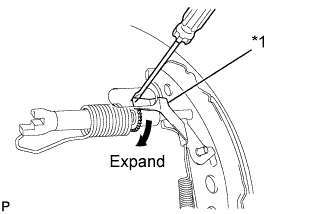
Text in Illustration *1 Automatic Adjust Lever Temporarily install the 2 wheel nuts.
-
Remove the shoe adjusting hole plug, and turn the adjuster to expand the shoe until the drum locks.
-
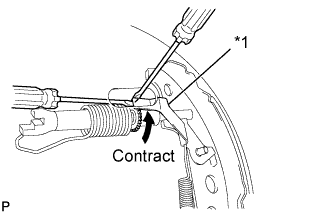
Text in Illustration *1 Automatic Adjust Lever Hold the automatic adjust lever away from the adjuster, and contract the brake shoe by turning the adjust bolt using another screwdriver until the drum can rotate smoothly.
Standard 11 notches -
Install the hole plug.
-
-
FILL RESERVOIR WITH BRAKE FLUID
-
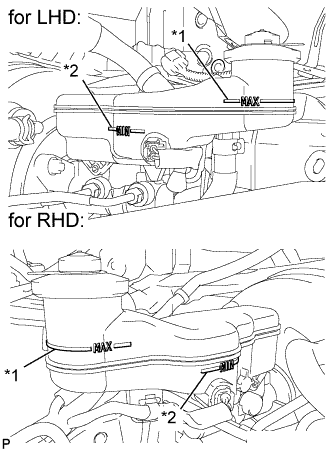
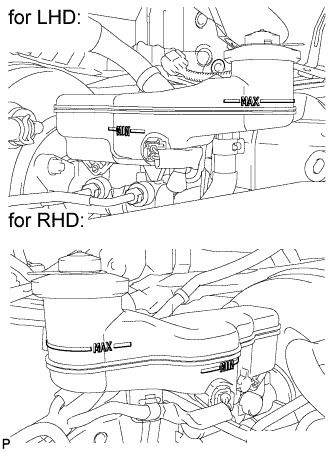
Text in Illustration *1 MAX Line *2 MIN Line Fill the reservoir with brake fluid.
Brake Fluid SAE J1703 or FMVSS No. 116 DOT 3 Note
Add brake fluid to keep the level between the MIN and MAX lines of the reservoir while bleeding the brakes.
-
-
BLEED BRAKE LINE
Note
-
Bleed the brake line of the wheel farthest from the master cylinder first.
-
Add brake fluid to keep the level between the MIN and MAX lines of the reservoir while bleeding the brakes.
-
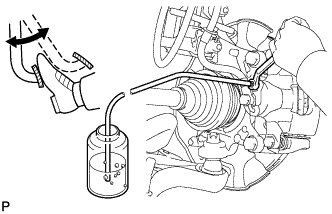
Connect a vinyl tube to the bleeder plug.
-
Depress the brake pedal several times, and then loosen the bleeder plug with the pedal depressed (Procedure 1).
-
When fluid stops coming out, tighten the bleeder plug, and then release the brake pedal (Procedure 2).
-
Repeat (Procedure 1) and (Procedure 2) until all the air in the fluid is completely bled out.
-
Tighten the bleeder plug completely.
- Torque:
- Front bleeder plug
- 8.3 N*m { 85 kgf*cm, 73 in.*lbf }
- Rear bleeder plug (for Disc Brake)
- 11 N*m { 112 kgf*cm, 8 ft.*lbf }
- Rear bleeder plug (for Drum Brake)
- 8.5 N*m { 87 kgf*cm, 75 in.*lbf }
-
Repeat the above procedure at each wheel to bleed the brake line.
-
-
INSPECT FOR BRAKE FLUID LEAK
-
INSPECT BRAKE FLUID LEVEL
-
Check the brake fluid level.
If brake fluid level is lower than the MIN line, check for leaks and inspect the disc brake pads. If necessary, refill the reservoir with brake fluid to the MAX line after repair or replacement.
Brake Fluid SAE J1703 or FMVSS No. 116 DOT 3
-
-
INSTALL REAR WHEEL
- Torque:
- 103 N*m { 1050 kgf*cm, 76 ft.*lbf }
-
TEMPORARILY TIGHTEN ADJUSTING NUT
-
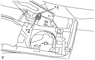
Text in Illustration *1 Lock Nut *2 Adjusting Nut Temporarily install the adjusting nut and the lock nut to the No. 1 parking brake cable assembly.
-
-
ADJUST PARKING BRAKE LEVER TRAVEL
-
Completely release the parking brake lever.
-
Text in Illustration *1 Lock Nut *2 Adjusting Nut Loosen the lock nut and the adjusting nut to completely release the parking brake cable.
-
Fully depress the brake pedal 3 to 5 times with the engine stopped.
-
Turn the adjusting nut until the parking brake lever travel is corrected to within the specified range.
Parking brake lever travel at 200 N (20 kgf, 45.0 lbf) Rear Brake Type Number of Clicks Disc 5 to 8 Drum 6 to 9 -
Using a wrench or an equivalent tool, hold the adjusting nut and tighten the lock nut.
- Torque:
- 6.0 N*m { 61 kgf*cm, 53 in.*lbf }
-
Operate the parking brake lever 3 to 4 times, and check the parking brake lever travel.
-
Check whether the parking brake drags or not.
-
-
INSTALL CONSOLE UPPER PANEL SUB-ASSEMBLY (for Manual Transaxle)
-
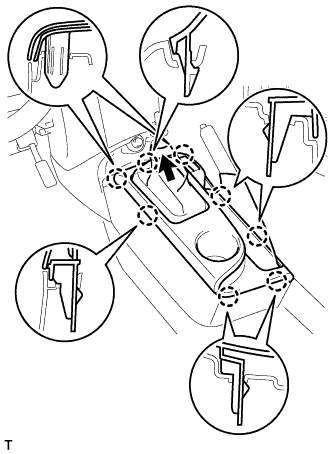
Install the shifting hole cover onto the shift lever.
-
Engage the 8 claws and install the console upper panel.
-
-
INSTALL CONSOLE UPPER PANEL SUB-ASSEMBLY (for CVT)
-
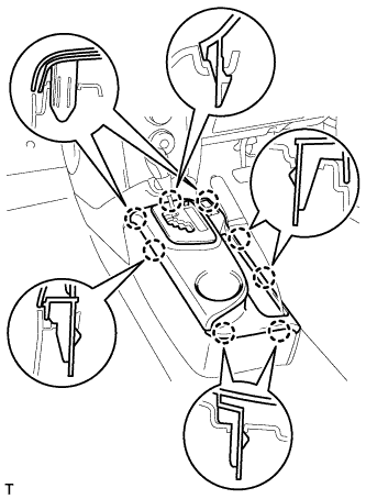
Engage the 8 claws and install the console upper panel.
-
-
INSTALL SHIFT LEVER KNOB SUB-ASSEMBLY (for Manual Transaxle)