REAR BRAKE (for Disc Type) INSTALLATION

-
INSTALL REAR DISC
-
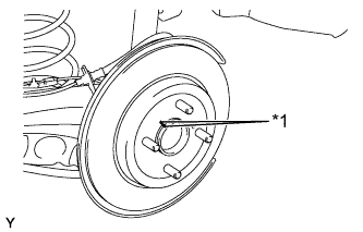
Text in Illustration *1 Matchmark Align the matchmarks of the disc and axle hub and install the disc.
Note
When replacing the disc with a new one, select the installation position where the rear disc has minimal runout.
-
-
INSTALL REAR DISC BRAKE CYLINDER MOUNTING
-
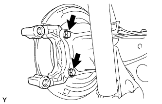
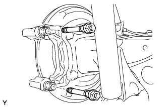
Install the rear disc brake cylinder mounting to the axle beam with the 2 bolts.
- Torque:
- 57 N*m { 585 kgf*cm, 42 ft.*lbf }
-
-
INSTALL REAR DISC BRAKE BUSHING DUST BOOT
-
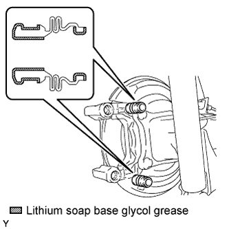
Apply a light layer of lithium soap base glycol grease to the entire circumference of 2 new rear disc brake bushing dust boots as shown in the illustration.
-
Install the 2 rear disc brake bushing dust boots to the rear disc brake cylinder mounting.
-
-
INSTALL REAR DISC BRAKE CYLINDER SLIDE BUSH
-
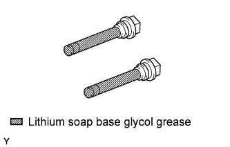
Install the 2 new slide bushes onto the 2 rear disc brake pad guide pins.
-
Apply a light layer of lithium soap base glycol grease to the entire circumference of the 2 rear disc brake pad guide pins as shown in the illustration.
-
-
INSTALL REAR DISC BRAKE PAD GUIDE PIN
-
Install the 2 rear disc brake pad guide pins to the rear disc brake cylinder mounting.
-
-
INSTALL REAR DISC BRAKE PAD SUPPORT PLATE
-
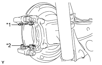
Text in Illustration *1 No. 1 Rear Disc Brake Pad Support Plate *2 No. 2 Rear Disc Brake Pad Support Plate Install the No. 1 rear disc brake pad support plate and No. 2 rear disc brake pad support plate to the rear disc brake cylinder mounting.
Note
Be sure to install each rear disc brake pad support plate in the correct position and direction.
-
-
INSTALL REAR DISC BRAKE ANTI SQUEAL SHIM KIT
-
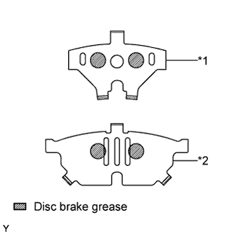
Text in Illustration *1 No. 1 Rear Disc Brake Anti Squeal Shim (Inner) *2 No. 1 Rear Disc Brake Anti Squeal Shim (Outer) Apply disc brake grease to the inside of the 2 No. 1 rear disc brake anti squeal shims as shown in the illustration.
-
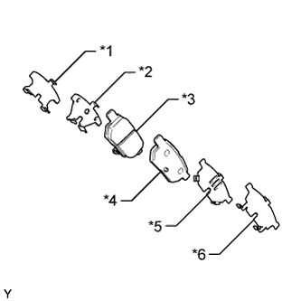
Text in Illustration *1 No. 2 Rear Disc Brake Anti Squeal Shim (Inner) *2 No. 1 Rear Disc Brake Anti Squeal Shim (Inner) *3 Rear Disc Brake Pad (w/ Indicator) *4 Rear Disc Brake Pad *5 No. 1 Rear Disc Brake Anti Squeal Shim (Outer) *6 No. 2 Rear Disc Brake Anti Squeal Shim (Outer) Install the 2 No. 1 rear disc brake anti squeal shims and 2 No. 2 rear disc brake anti squeal shims to each brake pad.
Note
-
When replacing worn pads, the anti squeal shims must be replaced together with the pads.
-
Apply disc brake grease to the area that contacts the anti squeal shim.
-
Disc brake grease may seep out slightly from the areas where the anti squeal shims are installed.
-
Make sure that disc brake grease is not applied onto the lining surface.
-
-
-
INSTALL REAR DISC BRAKE PAD KIT (PAD ONLY)
-
Install the 2 rear disc brake pads to the rear disc brake cylinder mounting.
Note
There should be no oil or grease on the friction surfaces of the disc brake pads or the rear disc.
-
-
INSTALL REAR DISC BRAKE CYLINDER ASSEMBLY
-
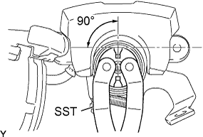
To compensate for pad wear when reusing the pad, use SST to push and turn the piston (LH side: counterclockwise, RH side: clockwise) to the position where the protrusion on the pad lines up properly with the piston groove.
- SST
- 09960-10010 ( 09963-00400 )
Note
Place the disc between the 2 brake pads and determine the piston return value.
-
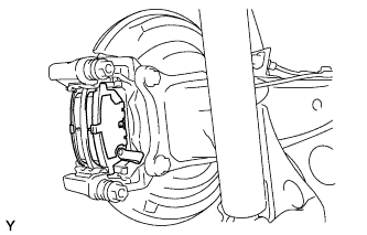
Hold the rear disc brake pad guide pin, and install the rear disc brake cylinder assembly to the rear disc brake cylinder mounting with the 2 bolts.
- Torque:
- 34 N*m { 350 kgf*cm, 25 ft.*lbf }
-
-
CONNECT REAR BRAKE FLEXIBLE HOSE
-
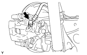
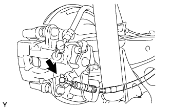
Connect the flexible hose to the rear disc brake cylinder assembly with the union bolt and a new gasket.
- Torque:
- 29 N*m { 296 kgf*cm, 21 ft.*lbf }
Tech Tips
Install the flexible hose lock securely into the lock hole in the disc brake cylinder.
-
-
CONNECT NO. 3 PARKING BRAKE CABLE ASSEMBLY
-
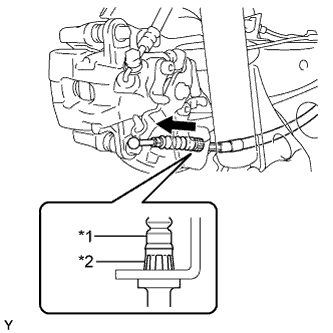
Text in Illustration *1 No. 3 Parking Brake Cable Assembly *2 Clip Insert the parking brake cable into the disc brake cylinder and engage the clip claws of the parking brake cable to the rear disc brake cylinder guide as shown in the illustration.
-
Connect the cable end to the rear disc brake cylinder operation lever.
-
-
FILL RESERVOIR WITH BRAKE FLUID
-
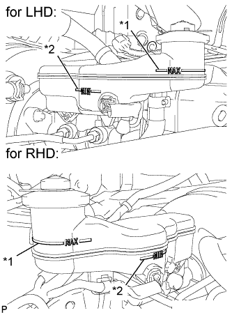
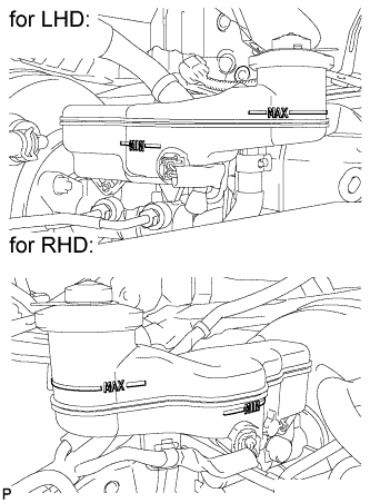
Text in Illustration *1 MAX Line *2 MIN Line Fill the reservoir with brake fluid.
Brake Fluid SAE J1703 or FMVSS No. 116 DOT 3 Note
Add brake fluid to keep the level between the MIN and MAX lines of the reservoir while bleeding the brakes.
-
-
BLEED BRAKE LINE
Note
-
Bleed the brake line of the wheel farthest from the master cylinder first.
-
Add brake fluid to keep the level between the MIN and MAX lines of the reservoir while bleeding the brakes.
-
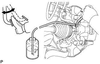
Connect a vinyl tube to the bleeder plug.
-
Depress the brake pedal several times, and then loosen the bleeder plug with the pedal depressed (Procedure 1).
-
When fluid stops coming out, tighten the bleeder plug, and then release the brake pedal (Procedure 2).
-
Repeat (Procedure 1) and (Procedure 2) until all the air in the fluid is completely bled out.
-
Tighten the bleeder plug completely.
- Torque:
- Front bleeder plug
- 8.3 N*m { 85 kgf*cm, 73 in.*lbf }
- Rear bleeder plug (for Disc Brake)
- 11 N*m { 112 kgf*cm, 8 ft.*lbf }
- Rear bleeder plug (for Drum Brake)
- 8.5 N*m { 87 kgf*cm, 75 in.*lbf }
-
Repeat the above procedure at each wheel to bleed the brake line.
-
-
INSPECT FOR BRAKE FLUID LEAK
-
INSPECT BRAKE FLUID LEVEL
-
Check the brake fluid level.
If brake fluid level is lower than the MIN line, check for leaks and inspect the disc brake pads. If necessary, refill the reservoir with brake fluid to the MAX line after repair or replacement.
Brake Fluid SAE J1703 or FMVSS No. 116 DOT 3
-
-
TEMPORARILY TIGHTEN ADJUSTING NUT
-
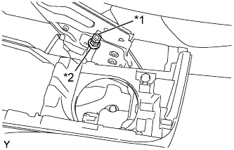
Text in Illustration *1 Lock Nut *2 Adjusting Nut Temporarily install the adjusting nut and the lock nut to the No. 1 parking brake cable assembly.
-
-
ADJUST PARKING BRAKE LEVER TRAVEL
-
Completely release the parking brake lever.
-
Text in Illustration *1 Lock Nut *2 Adjusting Nut Loosen the lock nut and the adjusting nut to completely release the parking brake cable.
-
Fully depress the brake pedal 3 to 5 times with the engine stopped.
-
Turn the adjusting nut until the parking brake lever travel is corrected to within the specified range.
Parking brake lever travel at 200 N (20 kgf, 45.0 lbf) Rear Brake Type Number of Clicks Disc 5 to 8 Drum 6 to 9 -
Using a wrench or an equivalent tool, hold the adjusting nut and tighten the lock nut.
- Torque:
- 6.0 N*m { 61 kgf*cm, 53 in.*lbf }
-
Operate the parking brake lever 3 to 4 times, and check the parking brake lever travel.
-
Check whether the parking brake drags or not.
-
-
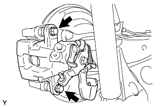
INSPECT REAR DISC BRAKE CYLINDER OPERATION LEVER AND STOPPER CLEARANCE
-
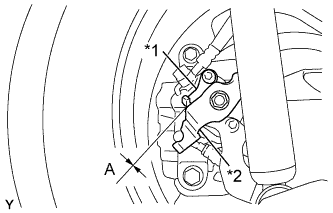
Text in Illustration *1 Stopper *2 Operation Lever Release the parking brake lever and check that the clearance measurement between the rear disc brake cylinder operation lever and the stopper is within the specified range.
Clearance A 0.5 mm (0.0197 in.) or less If the clearance is not within the specified range, replace the rear disc brake caliper assembly.
-
-
INSTALL REAR WHEEL
- Torque:
- 103 N*m { 1050 kgf*cm, 76 ft.*lbf }
-
INSTALL CONSOLE UPPER PANEL SUB-ASSEMBLY (for Manual Transaxle)
-
Install the shifting hole cover onto the shift lever.
-
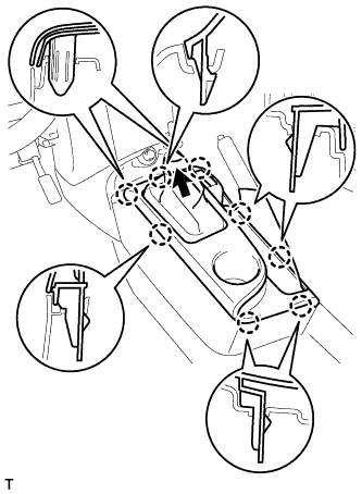
Engage the 8 claws and install the console upper panel.
-
-
INSTALL CONSOLE UPPER PANEL SUB-ASSEMBLY (for CVT)
-
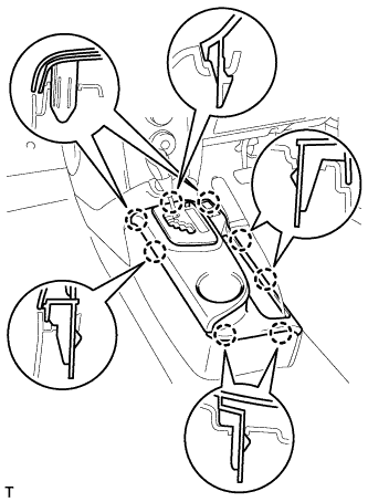
Engage the 8 claws and install the console upper panel.
-
-
INSTALL SHIFT LEVER KNOB SUB-ASSEMBLY (for Manual Transaxle)