BRAKE BOOSTER (for LHD) INSTALLATION

-
INSTALL CHECK VALVE GROMMET
-
Install a new check valve grommet to the brake booster assembly.
-
-
INSTALL BRAKE VACUUM CHECK VALVE ASSEMBLY
-
Install the vacuum check valve assembly to the brake booster assembly.
-
-
INSTALL BRAKE BOOSTER GASKET
-
Install a new brake booster gasket to the brake booster assembly.
-
-
INSTALL BRAKE BOOSTER ASSEMBLY
-
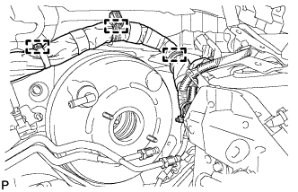
Install the brake booster assembly to the body with the 4 nuts.
- Torque:
- 13 N*m { 130 kgf*cm, 9 ft.*lbf }
Note
Do not damage the brake lines or fuel lines.
-
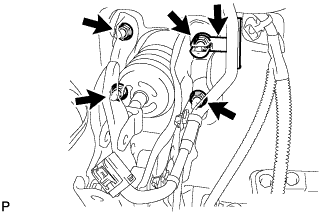
Install the wire harness clamp.
-
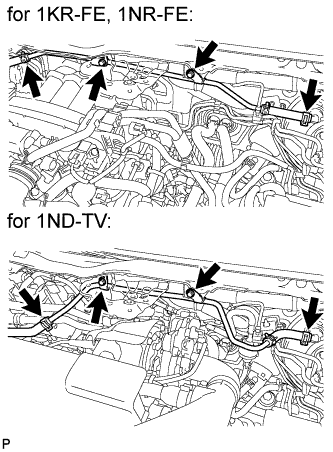
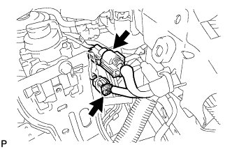
Engage the 3 clamps to install the wire harness to the body.
-
Engage the 2 new clamps to install the brake tube assembly to the body.
-
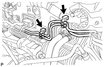
Using a union nut wrench (10 mm), connect the brake tube to the brake tube way.
- Torque:
- 15 N*m { 155 kgf*cm, 11 ft.*lbf }
Note
Use the formula to calculate special torque values for situations where a union nut wrench is combined with a torque wrench Click here.
-
-
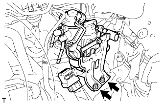
INSTALL HEATER PUMP ASSEMBLY (w/ Combustion Type Power Heater)
-
Install the heater pump with the nut.
- Torque:
- 7.5 N*m { 76 kgf*cm, 66 in.*lbf }
-
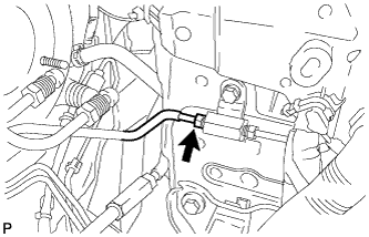
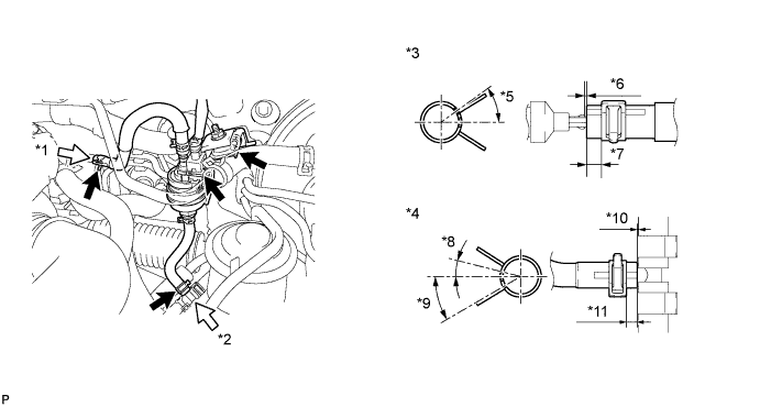
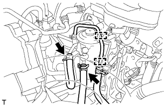
Install the fuel hose onto the fuel tube.
*1 A *7 2 to 7 mm (0.079 to 0.276 mm) *2 B *8 10° *3 View A *9 30° *4 View B *10 -3 to 0 mm (-0.118 to 0 mm) *5 30° *11 2 to 6 mm (0.079 to 0.236 mm) *6 -3 to 0 mm (-0.118 to 0 mm) - Tech Tips
Perform the installation with the hose clip and mark at the correct angle.
-
-
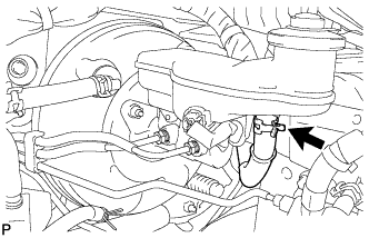
INSTALL NO. 1 HOSE TO HOSE TUBE
-
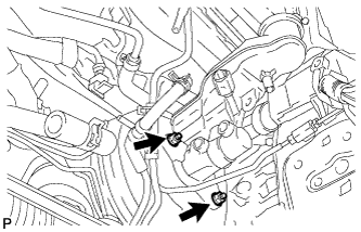
Install the hose tube onto the body with the 2 bolts.
- Torque:
- 7.8 N*m { 80 kgf*cm, 69 in.*lbf }
-
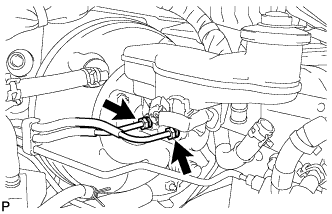
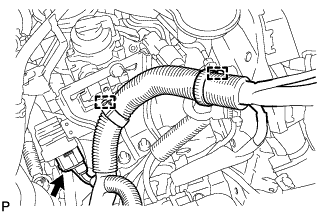
Connect the vacuum hose to the vacuum check valve and hose tube with the 2 clips.
-
-
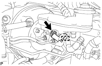
INSTALL BRAKE MASTER CYLINDER SUB-ASSEMBLY (w/o Stop and Start System)
-
Install a new O-ring to the brake master cylinder sub-assembly.
-
Install the brake master cylinder sub-assembly onto the brake booster.
Note
-
The master cylinder requires careful handling. Do not allow the master cylinder to receive any impact, such as from being dropped. Do not reuse a master cylinder that has been dropped.
-
Do not strike or pinch the master cylinder piston, and do not cause any damage to the master cylinder piston by any other means.
-
When installing the master cylinder to the brake booster, or when removing the master cylinder from the brake booster, make sure that the master cylinder is kept horizontal or its tip faces downward (the piston faces upward) to prevent the master cylinder piston from falling off.
-
Do not allow any foreign objects to contaminate the master cylinder piston. If a foreign object gets on the piston, remove it by using a piece of cloth and then apply an even layer of lithium soap base glycol grease around the circumference (sliding part) of the piston.
-
Do not use any other type of grease or fluid.
-
-
Install the 2 nuts.
- Torque:
- 13 N*m { 127 kgf*cm, 9 ft.*lbf }
-
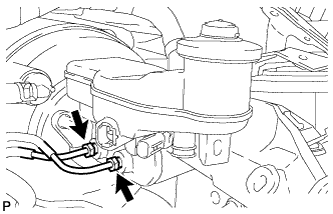
Using a union nut wrench (12 mm), connect the 2 brake tubes to the brake master cylinder sub-assembly.
- Torque:
- 20 N*m { 200 kgf*cm, 14 ft.*lbf }
Note
Use the formula to calculate special torque values for situations where a union nut wrench is combined with a torque wrench Click here.
-
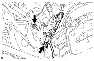
Engage the clamp and connect the brake fluid level warning switch connector.
-
-
INSTALL BRAKE MASTER CYLINDER SUB-ASSEMBLY (w/ Stop and Start System)
-
Install a new O-ring to the brake master cylinder sub-assembly.
-
Install the brake master cylinder sub-assembly onto the brake booster.
Note
-
The master cylinder requires careful handling. Do not allow the master cylinder to receive any impact, such as from being dropped. Do not reuse a master cylinder that has been dropped.
-
Do not strike or pinch the master cylinder piston, and do not cause any damage to the master cylinder piston by any other means.
-
When installing the master cylinder to the brake booster, or when removing the master cylinder from the brake booster, make sure that the master cylinder is kept horizontal or its tip faces downward (the piston faces upward) to prevent the master cylinder piston from falling off.
-
Do not allow any foreign objects to contaminate the master cylinder piston. If a foreign object gets on the piston, remove it by using a piece of cloth and then apply an even layer of lithium soap base glycol grease around the circumference (sliding part) of the piston.
-
Do not use any other type of grease or fluid.
-
-
Install the 2 nuts and vacuum sensor assembly.
- Torque:
- 13 N*m { 127 kgf*cm, 9 ft.*lbf }
-
Connect the vacuum hose.
-
Engage the clamp to install the vacuum sensor wire harness to the brake master cylinder sub-assembly.
-
Using a union nut wrench (12 mm), connect the 2 brake tubes to the brake master cylinder sub-assembly.
- Torque:
- 20 N*m { 200 kgf*cm, 14 ft.*lbf }
Note
Use the formula to calculate special torque values for situations where a union nut wrench is combined with a torque wrench Click here.
-
Engage the clamp and connect the brake fluid level warning switch connector and vacuum sensor wire connector.
-
-
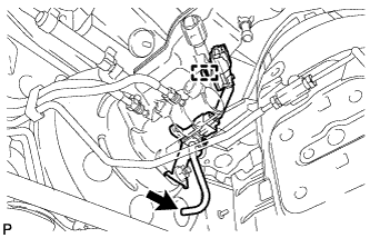
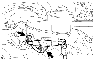
CONNECT CLUTCH RESERVOIR TUBE (for Manual Transaxle)
-
Connect the clutch reservoir tube to the brake master cylinder reservoir assembly with the clip.
-
-
INSTALL FUEL FILTER ASSEMBLY (for 1ND-TV)
-
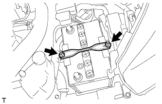
Install the fuel filter with the 2 nuts.
- Torque:
- 19 N*m { 189 kgf*cm, 14 ft.*lbf }
-
Connect the 2 fuel hose clamps to the fuel filter.
-
Connect the 2 fuel hoses to the fuel filter.
-
Connect the 2 connectors.
-
Connect the 2 wire harness clamps.
-
Connect the connector.
-
-
INSTALL BATTERY (for 1ND-TV)
-
INSTALL BATTERY CLAMP SUB-ASSEMBLY (for 1ND-TV)
-
Install the battery clamp with the 2 nuts.
- Torque:
- 3.5 N*m { 36 kgf*cm, 31 in.*lbf }
-
-
INSTALL BRAKE MASTER CYLINDER PUSH ROD CLEVIS
-
Provisionally install the push rod clevis onto the brake booster.
Tech Tips
Tighten the push rod lock nut when adjusting the brake pedal height.
-
Apply lithium soap base glycol grease to the push rod pin.
-
Install the push rod clevis onto the brake pedal with the push rod pin and new clip.
-
-
FILL RESERVOIR WITH BRAKE FLUID
-
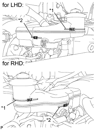
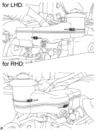
Text in Illustration *1 MAX Line *2 MIN Line Fill the reservoir with brake fluid.
Brake Fluid SAE J1703 or FMVSS No. 116 DOT 3 Note
Add brake fluid to keep the level between the MIN and MAX lines of the reservoir while bleeding the brakes.
-
-
BLEED CLUTCH LINE (for EE65)
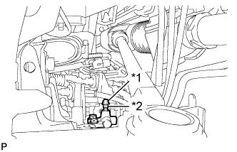
Text in Illustration *1 Bleeder plug cap *2 Bleeder plug Tech Tips
In case of clutch fluid replacement, make sure that the old fluid is replaced in the clutch line between the reservoir and the bleeder before bleeding.
-
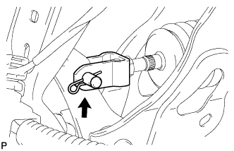
Remove the bleeder plug cap.
-
Connect a vinyl tube to the bleeder plug.
-
Depress the clutch pedal 5 times, and then loosen the bleeder plug while the pedal is depressed.
-
When fluid no longer comes out, tighten the bleeder plug, and then release the clutch pedal.
-
Repeat both of the previous 2 steps 6 times.
-
Tighten the bleeder plug.
- Torque:
- 8.4 N*m { 86 kgf*cm, 74 in.*lbf }
-
Depress the clutch pedal 10 times or more and confirm its operation.
Note
This must be performed before the engine is started.
-
Install the bleeder plug cap.
-
Check that all the air has been bled from the clutch line.
-
-
BLEED CLUTCH LINE (for EE53)
Text in Illustration *1 Bleeder plug cap *2 Bleeder plug Tech Tips
In case of clutch fluid replacement, make sure that the old fluid is replaced in the clutch line between the reservoir and the bleeder before bleeding.
-
Remove the bleeder plug cap.
-
Connect a vinyl tube to the bleeder plug.
-
Depress the clutch pedal 5 times, and then loosen the bleeder plug while the pedal is depressed.
-
When fluid no longer comes out, tighten the bleeder plug, and then release the clutch pedal.
-
Repeat both of the previous 2 steps 6 times.
-
Tighten the bleeder plug.
- Torque:
- 8.4 N*m { 86 kgf*cm, 74 in.*lbf }
-
Depress the clutch pedal 10 times or more and confirm its operation.
Note
This must be performed before the engine is started.
-
Install the bleeder plug cap.
-
Check that all the air has been bled from the clutch line.
-
-
BLEED CLUTCH LINE (for EE63)
Text in Illustration *1 Bleeder plug cap *2 Bleeder plug Tech Tips
In case of clutch fluid replacement, make sure that the old fluid is replaced in the clutch line between the reservoir and the bleeder before bleeding.
-
Remove the bleeder plug cap.
-
Connect a vinyl tube to the bleeder plug.
-
Depress the clutch pedal 5 times, and then loosen the bleeder plug while the pedal is depressed.
-
When fluid no longer comes out, tighten the bleeder plug, and then release the clutch pedal.
-
Repeat both of the previous 2 steps 6 times.
-
Tighten the bleeder plug.
- Torque:
- 8.4 N*m { 86 kgf*cm, 74 in.*lbf }
-
Depress the clutch pedal 10 times or more and confirm its operation.
Note
This must be performed before the engine is started.
-
Install the bleeder plug cap.
-
Check that all the air has been bled from the clutch line.
-
-
BLEED BRAKE MASTER CYLINDER
Note
-
If the master cylinder is reinstalled or if the reservoir becomes empty, bleed the master cylinder.
-
To prevent brake fluid from damaging painted surfaces, cover any surrounding parts with a piece of cloth.
-
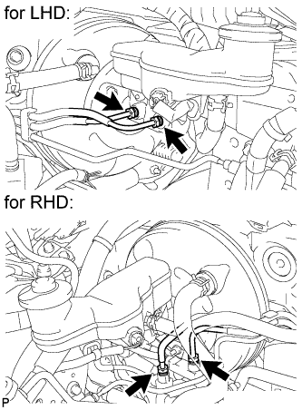
Using a union nut wrench (12 mm), disconnect the 2 brake tubes from the master cylinder.
-
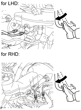
Slowly depress the brake pedal and hold it (Procedure 1).
-
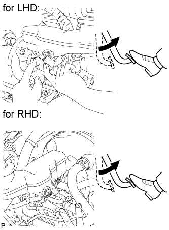
Cover the 2 outer holes with fingers, and release the brake pedal (Procedure 2).
-
Repeat (Procedure 1) and (Procedure 2), 3 or 4 times.
-
Using a union nut wrench (12 mm), connect the 2 brake tubes to the master cylinder.
- Torque:
- 20 N*m { 200 kgf*cm, 14 ft.*lbf }
Note
Use the formula to calculate special torque values for situations where a union nut wrench is combined with a torque wrench Click here.
-
-
BLEED BRAKE LINE
Note
-
Bleed the brake line of the wheel farthest from the master cylinder first.
-
Add brake fluid to keep the level between the MIN and MAX lines of the reservoir while bleeding the brakes.
-
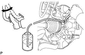
Connect a vinyl tube to the bleeder plug.
-
Depress the brake pedal several times, and then loosen the bleeder plug with the pedal depressed (Procedure 1).
-
When fluid stops coming out, tighten the bleeder plug, and then release the brake pedal (Procedure 2).
-
Repeat steps (Procedure 1) and (Procedure 2) until the new brake fluid comes out.
-
Tighten the bleeder plug completely.
- Torque:
- Front bleeder plug
- 8.3 N*m { 85 kgf*cm, 73 in.*lbf }
- Rear bleeder plug (for Disc Brake)
- 11 N*m { 112 kgf*cm, 8 ft.*lbf }
- Rear bleeder plug (for Drum Brake)
- 8.5 N*m { 87 kgf*cm, 75 in.*lbf }
-
Repeat the above procedure for each wheel to bleed the brake line.
-
-
BLEED BRAKE ACTUATOR
Note
-
After bleeding the air from the regular brake system, if the correct height or feel of the brake pedal cannot be obtained, perform air bleeding again by following the procedure below.
-
Bleeding air without the intelligent tester may lead to an injury or accident. When performing this procedure, always bleed air using the intelligent tester.
-
With the ignition switch off, depress the brake pedal several times to eliminate the vacuum pressure inside the booster.
-
Connect the intelligent tester to the DLC3 with the ignition switch off.
-
Turn the ignition switch to ON.
Note
Do not start the engine.
-
Turn the intelligent tester on.
-
Enter the following menus: Chassis / ABS/VSC/TRC / Utility / Air Bleeding.
-
Perform the bleeding at the right front wheel and left rear wheel (Procedure 1).
-
Bleed the Decrease Line.
-
Select "Decrease Line" on the intelligent tester menu display.
-
Depress the brake pedal.
-
Using the intelligent tester, operate the solenoid and at the same time, completely depress the brake pedal within 5 seconds.
Tech Tips
After operating the solenoid, the motor in the actuator operates for 5 seconds and during this time the brake pedal is pushed out.
-
Loosen the bleeder plug at the right front wheel.
Note
-
Loosen the bleeder plug at only one place.
-
Completely depress the brake pedal.
-
-
Tighten the bleeder plug, and then release the brake pedal.
- Torque:
- Front bleeder plug
- 8.3 N*m { 85 kgf*cm, 73 in.*lbf }
-
-
Bleed the Increase Line.
-
Perform brake line air bleeding at the right front wheel by depressing the brake pedal (Procedure 2).
-
Repeat (Procedure 2) until all air is completely bled out.
-
Perform the same procedure used at the right front wheel at the left rear wheel.
- Torque:
- Front bleeder plug
- 8.3 N*m { 85 kgf*cm, 73 in.*lbf }
- Rear bleeder plug (for Disc Brake)
- 11 N*m { 112 kgf*cm, 8 ft.*lbf }
- Rear bleeder plug (for Drum Brake)
- 8.5 N*m { 87 kgf*cm, 75 in.*lbf }
-
-
-
Repeat (Procedure 1) until the air is completely bled out.
-
Perform the same procedures for the left front wheel and right rear wheel line.
-
Repeat the brake line air bleeding procedure by depressing the brake pedal.
Note
Repeat the brake line air bleeding procedure at each wheel until the air is bled out.
-
-
INSPECT FOR BRAKE FLUID LEAK
-
INSPECT BRAKE FLUID LEVEL
-
Check the brake fluid level.
If brake fluid level is lower than the MIN line, check for leaks and inspect the disc brake pads. If necessary, refill the reservoir with brake fluid to the MAX line after repair or replacement.
Brake Fluid SAE J1703 or FMVSS No. 116 DOT 3
-
-
INSPECT AND ADJUST BRAKE PEDAL HEIGHT
-
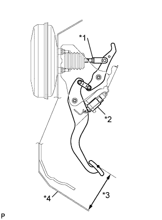
Text in Illustration *1 Push Rod Lock Nut *2 Stop Light Switch Assembly *3 Pedal Height *4 Dash Panel Inspect the brake pedal height.
Standard Pedal Height from Dash Panel Transaxle Type LHD RHD Manual Transaxle 135.2 to 145.2 mm (5.32 to 5.72 in.) 131.7 to 141.7 mm (5.19 to 5.58 in.) CVT 135.2 to 145.2 mm (5.32 to 5.72 in.) 132.7 to 142.7 mm (5.22 to 5.62 in.) -
Adjust the brake pedal height.
-
Disconnect the stop light switch connector.
-
Remove the stop light switch assembly.
-
Loosen the push rod lock nut.
-
Adjust the brake pedal height by turning the push rod.
-
Tighten the push rod lock nut.
- Torque:
- 26 N*m { 265 kgf*cm, 19 ft.*lbf }
-
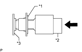
Text in Illustration *1 Adjuster *2 Stop Light Switch Assembly *3 Brake Pedal Insert the stop light switch into the adjuster until it just touches the brake pedal.
Note
Do not depress the brake pedal.
-
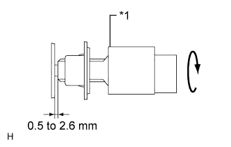
Text in Illustration *1 Stop Light Switch Assembly Make a quarter turn clockwise to install the stop light switch assembly.
-
Check the stop light switch clearance.
Stop light switch clearance 0.5 to 2.6 mm (0.0197 to 0.102 in.) -
Connect the stop light switch connector.
-
-
-
INSPECT BRAKE PEDAL FREE PLAY
-
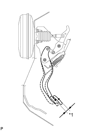
Text in Illustration *1 Pedal Free Play Push in the pedal until the beginning of the resistance is felt. Measure the pedal free play.
Standard Pedal Free Play 1 to 6 mm (0.0394 to 0.236 in.)
-
-
INSPECT BRAKE PEDAL RESERVE DISTANCE
Tech Tips
Measure the distance at the same point used for the brake pedal height inspection.
-
Release the parking brake lever.
With the engine running, depress the pedal and measure the pedal reserve distance.
Standard Pedal Reserve Distance from Dash Panel at 300 N (31 kgf, 67.4 lbf) Rear Brake Type Pedal Reserve Distance Disc More than 83 mm (3.27 in.) Drum More than 88 mm (3.46 in.) If the distance is not as specified, troubleshoot the brake system Click here.
-
-
BLEED AIR FROM FUEL SYSTEM (for 1ND-TV)
-
Bleed the fuel line Click here.
-
-
INSPECT FOR FUEL LEAK (for 1ND-TV)
-
INSTALL KNEE AIRBAG ASSEMBLY
-
Install the knee airbag assembly Click here.
-
-
INSTALL WINDSHIELD WIPER MOTOR AND LINK ASSEMBLY
-
Install the windshield wiper motor and link assembly Click here.
-