BRAKE ACTUATOR INSTALLATION

-
INSTALL BRAKE ACTUATOR BRACKET ASSEMBLY (for LHD)
-
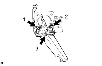
Install the brake actuator to the brake actuator bracket assembly with the 3 bolts.
- Torque:
- 5.4 N*m { 55 kgf*cm, 48 in.*lbf }
Note
-
Do not remove the hole plugs before installing a new brake actuator because the brake actuator is filled with brake fluid.
-
Do not carry the brake actuator by the connector.
-
Tighten the 3 bolts in the order shown in the illustration.
-
-
INSTALL BRAKE ACTUATOR BRACKET ASSEMBLY (for RHD)
-
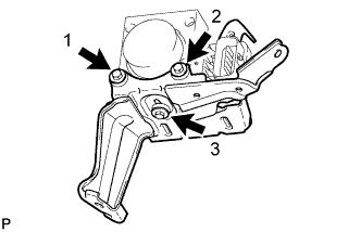
Install the brake actuator to the brake actuator bracket assembly with the 3 bolts.
- Torque:
- 5.4 N*m { 55 kgf*cm, 48 in.*lbf }
Note
-
Do not remove the hole plugs before installing a new brake actuator because the brake actuator is filled with brake fluid.
-
Do not carry the brake actuator by the connector.
-
Tighten the 3 bolts in the order shown in the illustration.
-
-
INSTALL BRAKE ACTUATOR WITH BRACKET (for LHD)
-
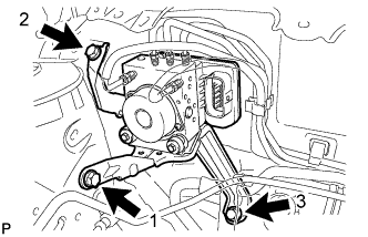
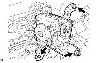
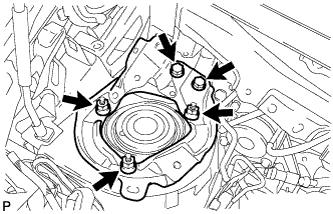
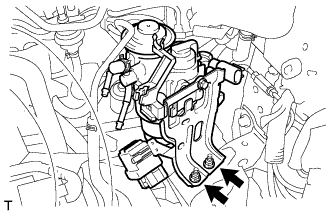
Install the brake actuator with bracket to the body with the 3 bolts.
- Torque:
- 19 N*m { 194 kgf*cm, 14 ft.*lbf }
Note
-
Do not damage the brake lines or wire harness.
-
Tighten the 3 bolts in the order shown in the illustration.
-
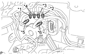
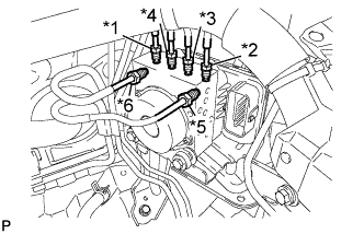
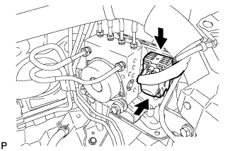
Text in Illustration *1 To Front Wheel Cylinder RH *2 To Front Wheel Cylinder LH *3 To Rear Wheel Cylinder RH *4 To Rear Wheel Cylinder LH *5 From 1st of Master Cylinder *6 From 2nd of Master Cylinder Temporarily tighten each brake tube to the correct positions of the brake actuator as shown in the illustration.
-
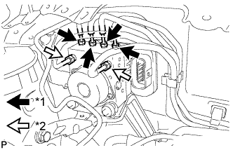
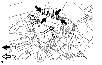
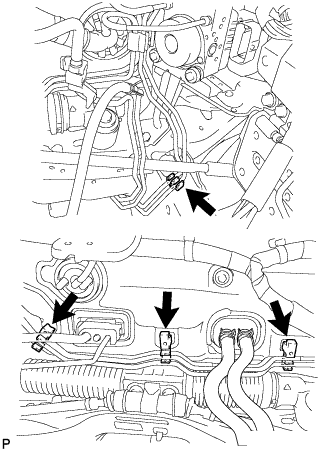
Text in Illustration *1 Flare Nut ( 10 mm) *2 Flare Nut ( 12 mm) Using a union nut wrench (10 mm and 12 mm), fully tighten each brake tube.
- Torque:
- Flare Nut (10 mm)
- 15 N*m { 155 kgf*cm, 11 ft.*lbf }
- Flare Nut (12 mm)
- 20 N*m { 200 kgf*cm, 14 ft.*lbf }
Note
Use the formula to calculate special torque values for situations where a union nut wrench is combined with a torque wrench Click here.
-
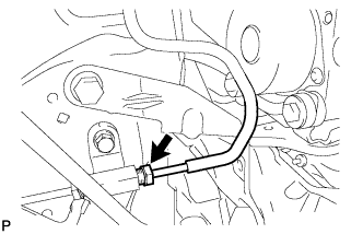
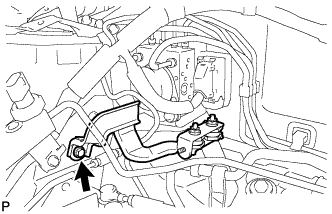
Using a union nut wrench (10 mm), connect the No. 3 brake tube to the brake tube way.
- Torque:
- 15 N*m { 155 kgf*cm, 11 ft.*lbf }
Note
Use the formula to calculate special torque values for situations where a union nut wrench is combined with a torque wrench Click here.
-
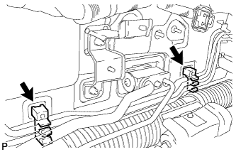
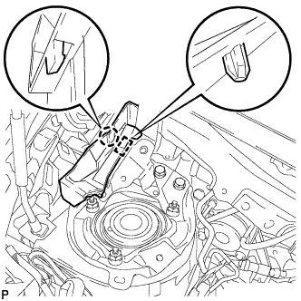
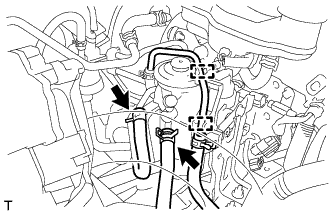
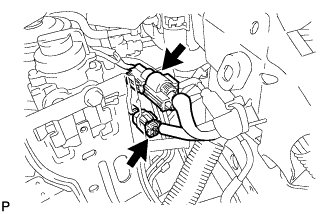
Engage the 2 new clamps to install the brake tube assembly to the body.
-
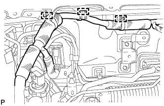
Engage the 3 clamps to install the wire harness to the body.
-
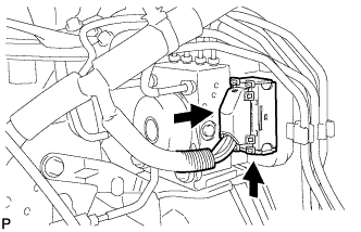
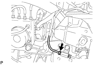
Connect the actuator connector.
Note
Make sure that the connector is locked securely.
-
-
INSTALL BRAKE ACTUATOR WITH BRACKET (for RHD)
-
Install the brake actuator with bracket to the body with the 3 bolts.
- Torque:
- 19 N*m { 194 kgf*cm, 14 ft.*lbf }
Note
-
Do not damage the brake lines or wire harness.
-
Tighten the 3 bolts in the order shown in the illustration.
-
Text in Illustration *1 To Front Wheel Cylinder RH *2 To Front Wheel Cylinder LH *3 To Rear Wheel Cylinder RH *4 To Rear Wheel Cylinder LH *5 From 1st of Master Cylinder *6 From 2nd of Master Cylinder Temporarily tighten each brake tube to the correct positions of the brake actuator with bracket as shown in the illustration.
-
Text in Illustration *1 Flare Nut ( 10 mm) *2 Flare Nut ( 12 mm) Using a union nut wrench (10 mm and 12 mm), fully tighten each brake tube.
- Torque:
- Flare Nut (10 mm)
- 15 N*m { 155 kgf*cm, 11 ft.*lbf }
- Flare Nut (12 mm)
- 20 N*m { 200 kgf*cm, 14 ft.*lbf }
Note
Use the formula to calculate special torque values for situations where a union nut wrench is combined with a torque wrench Click here.
-
Using a union nut wrench (10 mm), connect the No. 5 brake tube to the brake tube way.
- Torque:
- 15 N*m { 155 kgf*cm, 11 ft.*lbf }
Note
Use the formula to calculate special torque values for situations where a union nut wrench is combined with a torque wrench Click here.
-
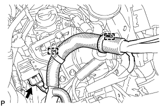
Engage the 4 new clamps to install the brake tube assembly to the body.
-
Connect the actuator connector.
Note
Make sure that the connector is locked securely.
-
-
INSTALL FRONT FENDER EXTENSION RH (for LHD)
-
Install the front fender extension RH to the body with the 2 bolts and 2 nuts.
- Torque:
- bolt
- 17 N*m { 175 kgf*cm, 13 ft.*lbf }
- nut
- 39 N*m { 398 kgf*cm, 29 ft.*lbf }
-
-
INSTALL COWL VENTILATOR SPLASH SHIELD RH (for LHD)
-
Engage the guide and claw to install the cowl ventilator splash shield RH.
-
-
INSTALL NO. 2 HEATER BRACKET SUB-ASSEMBLY (w/ Combustion Type Power Heater)
-
Install the No. 2 heater bracket sub-assembly with the bolt.
- Torque:
- 7.5 N*m { 76 kgf*cm, 66 in.*lbf }
-
-
INSTALL HEATER ASSEMBLY (w/ Combustion Type Power Heater)
-
Install the heater assembly Click here.
-
-
INSTALL FUEL FILTER ASSEMBLY (for 1ND-TV RHD)
-
Install the fuel filter with the 2 nuts.
- Torque:
- 19 N*m { 189 kgf*cm, 14 ft.*lbf }
-
Connect the 2 fuel hose clamps to the fuel filter.
-
Connect the 2 fuel hoses to the fuel filter.
-
Connect the 2 connectors.
-
Connect the 2 wire harness clamps.
-
Connect the connector.
-
-
INSTALL BATTERY (for 1ND-TV RHD)
-
INSTALL BATTERY CLAMP SUB-ASSEMBLY (for 1ND-TV RHD)
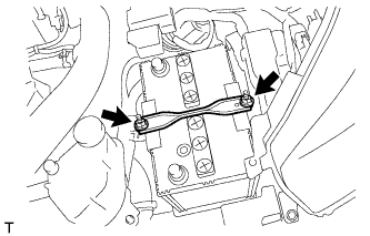
-
Install the battery clamp with the 2 nuts.
- Torque:
- 3.5 N*m { 36 kgf*cm, 31 in.*lbf }
-
-
CONNECT CABLE TO NEGATIVE BATTERY TERMINAL
- Torque:
- 5.4 N*m { 55 kgf*cm, 48 in.*lbf }
-
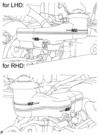
FILL RESERVOIR WITH BRAKE FLUID
-
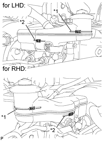
Text in Illustration *1 MAX Line *2 MIN Line Fill the reservoir with brake fluid.
Brake Fluid SAE J1703 or FMVSS No. 116 DOT 3 Note
Add brake fluid to keep the level between the MIN and MAX lines of the reservoir while bleeding the brakes.
-
-
BLEED BRAKE MASTER CYLINDER
Note
-
If the master cylinder is reinstalled or if the reservoir becomes empty, bleed the master cylinder.
-
To prevent brake fluid from damaging painted surfaces, cover any surrounding parts with a piece of cloth.
-
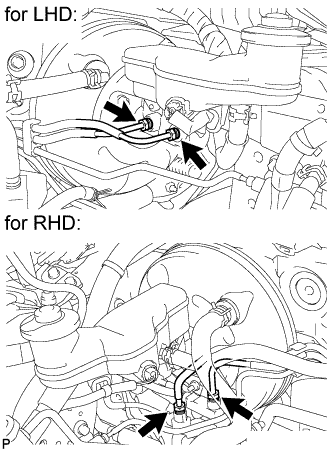
Using a union nut wrench (12 mm), disconnect the 2 brake tubes from the master cylinder.
-
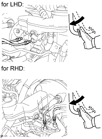
Slowly depress the brake pedal and hold it (Procedure 1).
-
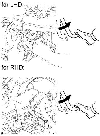
Cover the 2 outer holes with fingers, and release the brake pedal (Procedure 2).
-
Repeat (Procedure 1) and (Procedure 2), 3 or 4 times.
-
Using a union nut wrench (12 mm), connect the 2 brake tubes to the master cylinder.
- Torque:
- 20 N*m { 200 kgf*cm, 14 ft.*lbf }
Note
Use the formula to calculate special torque values for situations where a union nut wrench is combined with a torque wrench Click here.
-
-
BLEED BRAKE LINE
Note
-
Bleed the brake line of the wheel farthest from the master cylinder first.
-
Add brake fluid to keep the level between the MIN and MAX lines of the reservoir while bleeding the brakes.
-
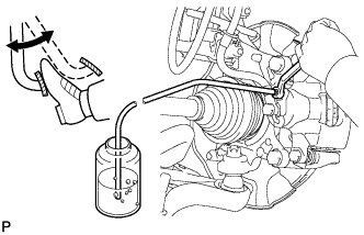
Connect a vinyl tube to the bleeder plug.
-
Depress the brake pedal several times, and then loosen the bleeder plug with the pedal depressed (Procedure 1).
-
When fluid stops coming out, tighten the bleeder plug, and then release the brake pedal (Procedure 2).
-
Repeat (Procedure 1) and (Procedure 2) until all the air in the fluid is completely bled out.
-
Tighten the bleeder plug completely.
- Torque:
- Front bleeder plug
- 8.3 N*m { 85 kgf*cm, 73 in.*lbf }
- Rear bleeder plug (for Disc Brake)
- 11 N*m { 112 kgf*cm, 8 ft.*lbf }
- Rear bleeder plug (for Drum Brake)
- 8.5 N*m { 87 kgf*cm, 75 in.*lbf }
-
Repeat the above procedure at each wheel to bleed the brake line.
-
-
BLEED BRAKE ACTUATOR
Note
-
After bleeding the air from the regular brake system, if the correct height or feel of the brake pedal cannot be obtained, perform air bleeding again by following the procedure below.
-
Bleeding air without the intelligent tester may lead to an injury or accident. When performing this procedure, always bleed air using the intelligent tester.
-
With the ignition switch off, depress the brake pedal several times to eliminate the vacuum pressure inside the booster.
-
Connect the intelligent tester to the DLC3 with the ignition switch off.
-
Turn the ignition switch to ON.
Note
Do not start the engine.
-
Turn the intelligent tester on.
-
Enter the following menus: Chassis / ABS/VSC/TRC / Utility / Air Bleeding.
-
Perform the bleeding at the right front wheel and left rear wheel (Procedure 1).
-
Bleed the Decrease Line.
-
Select "Decrease Line" on the intelligent tester menu display.
-
Depress the brake pedal.
-
Using the intelligent tester, operate the solenoid and at the same time, completely depress the brake pedal within 5 seconds.
Tech Tips
After operating the solenoid, the motor in the actuator operates for 5 seconds and during this time the brake pedal is pushed out.
-
Loosen the bleeder plug at the right front wheel.
Note
-
Loosen the bleeder plug at only one place.
-
Completely depress the brake pedal.
-
-
Tighten the bleeder plug, and then release the brake pedal.
- Torque:
- Front bleeder plug
- 8.3 N*m { 85 kgf*cm, 73 in.*lbf }
-
-
Bleed the Increase Line.
-
Perform brake line air bleeding at the right front wheel by depressing the brake pedal (Procedure 2).
-
Repeat (Procedure 2) until all air is completely bled out.
-
Perform the same procedure used at the right front wheel at the left rear wheel.
- Torque:
- Front bleeder plug
- 8.3 N*m { 85 kgf*cm, 73 in.*lbf }
- Rear bleeder plug (for Disc Brake)
- 11 N*m { 112 kgf*cm, 8 ft.*lbf }
- Rear bleeder plug (for Drum Brake)
- 8.5 N*m { 87 kgf*cm, 75 in.*lbf }
-
-
-
Repeat (Procedure 1) until the air is completely bled out.
-
Perform the same procedures for the left front wheel and right rear wheel line.
-
Repeat the brake line air bleeding procedure by depressing the brake pedal.
Note
Repeat the brake line air bleeding procedure at each wheel until the air is bled out.
-
-
INSPECT FOR BRAKE FLUID LEAK
-
INSPECT BRAKE FLUID LEVEL
-
Check the brake fluid level.
If brake fluid level is lower than the MIN line, check for leaks and inspect the disc brake pads. If necessary, refill the reservoir with brake fluid to the MAX line after repair or replacement.
Brake Fluid SAE J1703 or FMVSS No. 116 DOT 3
-
-
BLEED AIR FROM FUEL SYSTEM (for 1ND-TV RHD)
-
Bleed the fuel line Click here.
-
-
INSPECT FOR FUEL LEAK (for 1ND-TV RHD)
-
INSTALL COWL PANEL SUB-ASSEMBLY
-
Install the cowl panel sub-assembly Click here.
-
-
INSPECT ACTUATOR WITH INTELLIGENT TESTER
Tech Tips