VEHICLE STABILITY CONTROL SYSTEM TS and CG Terminal Circuit
DESCRIPTION
In the Test Mode (signal check), a malfunction in the speed sensor that cannot be detected when the vehicle is stopped can be detected while driving.
Transition to the sensor check mode can be performed by connecting terminals TS and CG of the DLC3 and turning the ignition switch from off to ON.
WIRING DIAGRAM
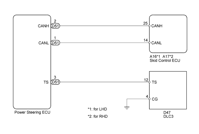
INSPECTION PROCEDURE
Note
When replacing the brake actuator assembly, perform zero point calibration Click here.
PROCEDURE
-
CHECK CAN COMMUNICATION SYSTEM
-
Check if CAN communication system DTCs are output Click here.
Result Result Proceed to DTC not output A DTC output B
B 
CHECK CAN COMMUNICATION SYSTEM Click here
A 
-
-
INSPECT DLC3
-
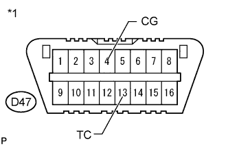
*1 Front view of DLC3 Turn the ignition switch to ON.
-
Measure the voltage according to the value(s) in the table below.
Standard Voltage Tester Connection Switch Condition Specified Condition D47-12 (TS) - D47-4 (CG) Ignition switch ON 11 to 14 V Result Result Proceed to NG A OK B
B 
CHECK POWER STEERING ECU (TS of DLC3 INPUT) Click here
A
-
-
CHECK HARNESS AND CONNECTOR (TS of DLC3 - POWER STEERING ECU)
-
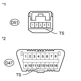
*1 Front view of wire harness connector
(to Power Steering ECU)
*2 Front view of DLC3 Turn the ignition switch off.
-
Disconnect the ECM connector.
-
Measure the resistance according to the value(s) in the table below.
Standard Resistance Tester Connection Condition Specified Condition D47-12 (TS) - D51-3 (TS) Always Below 1 Ω D47-12 (TS) - Body ground Always 10 kΩ or higher
NG
REPAIR OR REPLACE HARNESS OR CONNECTOR
OK
-
-
CHECK HARNESS AND CONNECTOR (CG of DLC3 - BODY GROUND)
-
Measure the resistance according to the value(s) in the table below.
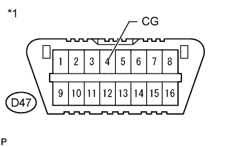
Standard Resistance *1 Front view of DLC3 Tester Connection Condition Specified Condition D47-4 (CG) - Body ground Always Below 1 Ω
NG
REPAIR OR REPLACE HARNESS OR CONNECTOR
OK
-
-
CHECK POWER STEERING ECU (TS of DLC3 INPUT)
-
*1 Front view of DLC3 Turn the ignition switch off.
-
Reconnect the power steering ECU connector.
-
Using SST, connect terminals TS and CG of the DLC3.
-
Turn the ignition switch to ON.
-
Check that the PS warning light is blinking.
Result Result Proceed to Check PS warning light is blinking A Check PS warning light is not blinking B
B
CHECK POWER STEERING SYSTEM Click here
A 
REPLACE BRAKE ACTUATOR ASSEMBLY Click here
-