VEHICLE STABILITY CONTROL SYSTEM Skid Control Buzzer Circuit
DESCRIPTION
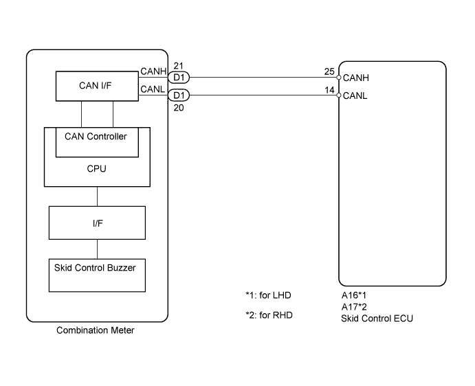
The skid control ECU is connected to the combination meter via CAN communication.
The combination meter has a built-in skid control buzzer. The skid control buzzer sounds during VSC operation.
WIRING DIAGRAM
INSPECTION PROCEDURE
Note
When replacing the brake actuator assembly, perform zero point calibration Click here.
PROCEDURE
-
CHECK CAN COMMUNICATION SYSTEM
-
Check if CAN communication system DTCs are output Click here.
Result Result Proceed to DTC not output A DTC output B
B 
CHECK CAN COMMUNICATION SYSTEM Click here
A 
-
-
PERFORM ACTIVE TEST USING INTELLIGENT TESTER (SKID CONTROL BUZZER)
-
Connect the intelligent tester to the DLC3.
-
Start the engine.
-
Enter the following menus: Chassis / ABS/VSC/TRC / Active Test.
ABS/VSC/TRC (Skid Control ECU) Tester Display Test Part Control Range Diagnostic Note Buzzer Skid control buzzer Buzzer ON/OFF Buzzer can be heard -
Check that the buzzer sounds or stops in accordance with the intelligent tester.
Result Result Proceed to Buzzer does not sound or stop constantly A Buzzer sounds and stops B
B
REPLACE BRAKE ACTUATOR ASSEMBLY Click here
A
-
-
REPLACE COMBINATION METER ASSEMBLY
-
Turn the ignition switch off.
-
Replace the combination meter Click here.
NEXT
-
-
PERFORM ACTIVE TEST USING INTELLIGENT TESTER (SKID CONTROL BUZZER)
-
Connect the intelligent tester to the DLC3.
-
Start the engine.
-
Enter the following menus: Chassis / ABS/VSC/TRC / Active Test.
ABS/VSC/TRC (Skid Control ECU) Tester Display Test Part Control Range Diagnostic Note Buzzer Skid control buzzer Buzzer ON/OFF Buzzer can be heard -
Check that the buzzer sounds or stops in accordance with the intelligent tester.
Result Result Proceed to Buzzer does not sound or stop constantly A Buzzer sounds and stops B
B
END
A 
REPLACE BRAKE ACTUATOR ASSEMBLY Click here
-