BRAKE PEDAL INSTALLATION

-
INSTALL BRAKE PEDAL SUPPORT SUB-ASSEMBLY (for LHD)
-
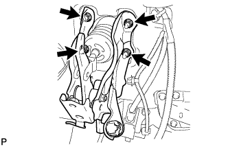
Install the brake pedal support sub-assembly with the 4 nuts.
- Torque:
- 13 N*m { 130 kgf*cm, 9 ft.*lbf }
-
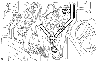
Engage the 3 clamps to the brake pedal support sub-assembly.
-
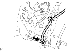
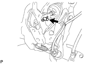
Connect the connector to the stop light switch assembly.
-
-
INSTALL BRAKE PEDAL SUPPORT SUB-ASSEMBLY (for RHD)
-
Install the brake pedal support sub-assembly with the 4 nuts.
- Torque:
- 13 N*m { 130 kgf*cm, 9 ft.*lbf }
-
Engage the clamp to the brake pedal support sub-assembly.
-
Connect the connector to the stop light switch assembly.
-
-
INSTALL PUSH ROD PIN
-
Apply lithium soap base glycol grease to the inner surface of the hole on the brake pedal lever.
-
Connect the brake master cylinder push rod clevis to the brake pedal support sub-assembly with the push rod pin and a new clip.
-
-
INSPECT AND ADJUST BRAKE PEDAL HEIGHT
-
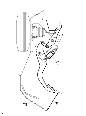
Text in Illustration *1 Push Rod Lock Nut *2 Stop Light Switch Assembly *3 Floor Panel *a Pedal Height Inspect the brake pedal height.
Standard Pedal Height from Floor Panel Transaxle Type LHD RHD Manual Transaxle 140.4 to 150.4 mm (5.53 to 5.92 in.) 136.4 to 146.4 mm (5.38 to 5.76 in.) CVT 140.4 to 150.4 mm (5.53 to 5.92 in.) 137.5 to 147.5 mm (5.42 to 5.80 in.) -
Adjust the brake pedal height.
-
Disconnect the stop light switch connector.
-
Remove the stop light switch assembly.
-
Loosen the push rod lock nut.
-
Adjust the brake pedal height by turning the push rod.
-
Tighten the push rod lock nut.
- Torque:
- 26 N*m { 265 kgf*cm, 19 ft.*lbf }
-
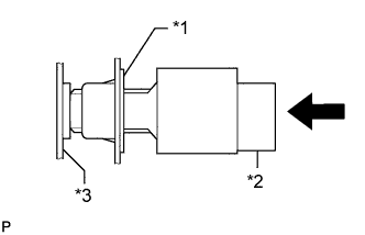
Text in Illustration *1 Adjuster *2 Stop Light Switch Assembly *3 Brake Pedal Insert the stop light switch into the adjuster until it just touches the brake pedal.
Note
Do not depress the brake pedal.
-
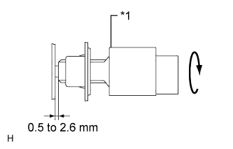
Text in Illustration *1 Stop Light Switch Assembly Make a quarter turn clockwise to install the stop light switch assembly.
- Torque:
- 1.5 N*m { 15 kgf*cm, 13 in.*lbf, or less }
-
Check the stop light switch clearance.
Stop light switch clearance 0.5 to 2.6 mm (0.0197 to 0.102 in.) -
Connect the stop light switch connector.
-
-
-
INSPECT BRAKE PEDAL FREE PLAY
-
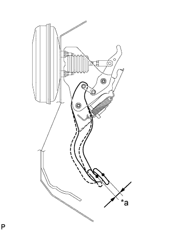
Text in Illustration *a Pedal Free Play Push in the pedal until the beginning of the resistance is felt. Measure the pedal free play.
Standard Pedal Free Play 1 to 6 mm (0.0394 to 0.236 in.)
-
-
INSPECT BRAKE PEDAL RESERVE DISTANCE
Tech Tips
Measure the distance at the same point used for the brake pedal height inspection.
-
Release the parking brake lever.
With the engine running, depress the pedal and measure the pedal reserve distance.
Standard Pedal Reserve Distance from Floor Panel at 300 N (31 kgf, 67.4 lbf) Rear Brake Type Pedal Reserve Distance Disc More than 86 mm (3.39 in.) Drum More than 91 mm (3.59 in.) If the distance is not as specified, troubleshoot the brake system Click here.
-
-
INSTALL INSTRUMENT PANEL REINFORCEMENT ASSEMBLY
-
Install the instrument panel reinforcement assembly Click here.
-