VEHICLE STABILITY CONTROL SYSTEM, Diagnostic DTC:C1425

| DTC Code | DTC Name |
|---|---|
| C1425 | Open in Stop Light Switch Circuit |
DESCRIPTION
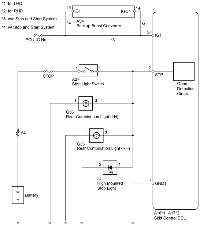
The skid control ECU detects the brake operating conditions through a signal transmitted by the stop light switch.
The skid control ECU has an open detection circuit, which outputs this DTC when detecting an open in the stop light input line or the ground line of the stop light circuit with the stop light switch off (brake pedal not depressed).
On vehicles equipped with the Stop and Start System, DTC may be output if there is a significant difference between IG power source voltage and backup boost converter power source voltage when the stop and start system is cranking the engine during restarting.
| DTC Code | DTC Detection Condition | Trouble Area |
|---|---|---|
| C1425 | When IG1 terminal voltage is between 9.5 and 17.4 V, an open stop light switch circuit continues for 3 seconds or more. |
|
WIRING DIAGRAM
INSPECTION PROCEDURE
Note
-
When replacing the brake actuator assembly, perform zero point calibration Click here.
-
Inspect the fuses for circuits related to this system before performing the following inspection procedure.
PROCEDURE
-
READ VALUE USING INTELLIGENT TESTER (STOP LIGHT SWITCH)
-
Connect the intelligent tester to the DLC3.
-
Turn the ignition switch to ON.
-
Enter the following menus: Chassis / ABS/VSC/TRC / Data List.
ABS/VSC/TRC (Skid Control ECU) Tester Display Measurement Item/Range Normal Condition Diagnostic Note Stop Light SW Stop light switch/ON or OFF ON: Brake pedal depressed
OFF: Brake pedal released
- -
Check that the stop light switch display observed on the intelligent tester changes according to brake pedal operation.
OK The intelligent tester displays ON or OFF according to brake pedal operation.
NG 
INSPECT STOP LIGHT SWITCH (POWER SOURCE TERMINAL) Click here
OK 
-
-
RECONFIRM DTC
-
Turn the ignition switch off.
-
Clear the DTCs Click here.
-
Start the engine.
-
Depress the brake pedal several times to test the stop light circuit.
-
Check if the same DTC is recorded Click here.
Result Result Proceed to DTC (C1425) is not output A DTC (C1425) is output B Tech Tips
If troubleshooting has been carried out according to the Problem Symptoms Table, refer back to the table and proceed to the next step Click here.
B 
REPLACE BRAKE ACTUATOR ASSEMBLY Click here
A 
CHECK FOR INTERMITTENT PROBLEMS (SYMPTOM SIMULATION) Click here
-
-
INSPECT STOP LIGHT SWITCH (POWER SOURCE TERMINAL)
-
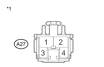
Text in Illustration *1 Front view of wire harness connector
(to Stop Light Switch)
Make sure that there is no looseness at the locking part and the connecting part of the connectors.
-
Disconnect the A27 stop light switch connector.
-
Measure the voltage according to the value(s) in the table below.
Standard Voltage Tester Connection Condition Specified Condition A27-2 - Body ground Always 11 to 14 V
NG
REPAIR OR REPLACE HARNESS OR CONNECTOR (POWER SOURCE CIRCUIT)
OK
-
-
INSPECT STOP LIGHT SWITCH
-
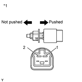
Text in Illustration *1 Component without harness connected
(Stop Light Switch)
Measure the resistance according to the value(s) in the table below.
Standard Resistance Tester Connection Switch Condition Specified Condition 1 - 2 Switch pin free Below 1 Ω 1 - 2 Switch pin pushed in 10 kΩ or higher
NG
REPLACE STOP LIGHT SWITCH Click here
OK
-
-
CHECK HARNESS AND CONNECTOR (STP TERMINAL)
-
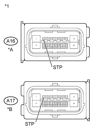
Text in Illustration *A for LHD *B for RHD *1 Front view of wire harness connector
(to Skid Control ECU)
Turn the ignition switch off.
-
Make sure that there is no looseness at the locking part and the connecting part of the connectors.
-
Disconnect the skid control ECU connector.
-
Measure the voltage according to the value(s) in the table below.
Standard Voltage for LHD Tester Connection Switch Condition Specified Condition A16-2 (STP) - Body ground Stop light switch ON
(Brake pedal depressed)
8 to 14 V A16-2 (STP) - Body ground Stop light switch OFF
(Brake pedal released)
Below 1.5 V for RHD Tester Connection Switch Condition Specified Condition A17-2 (STP) - Body ground Stop light switch ON
(Brake pedal depressed)
8 to 14 V A17-2 (STP) - Body ground Stop light switch OFF
(Brake pedal released)
Below 1.5 V
NG
REPAIR OR REPLACE HARNESS OR CONNECTOR
OK
REPLACE BRAKE ACTUATOR ASSEMBLY Click here
-