VEHICLE STABILITY CONTROL SYSTEM VSC OFF Indicator Light Remains ON
DESCRIPTION
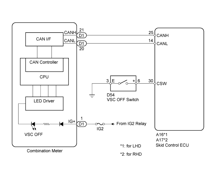
The skid control ECU is connected to the combination meter via CAN communication.
Pressing the VSC OFF switch turns off traction control and pressing and holding this switch turns off traction and VSC controls. If VSC control turns OFF, the VSC OFF indicator light will come on.
The VSC OFF indicator light will blink when the skid control ECU stores a DTC.
WIRING DIAGRAM
INSPECTION PROCEDURE
Note
When replacing the brake actuator assembly, perform zero point calibration Click here.
PROCEDURE
-
CHECK CAN COMMUNICATION SYSTEM
-
Check if CAN communication system DTCs are output Click here.
Result Result Proceed to DTC not output A DTC output B
B 
CHECK CAN COMMUNICATION SYSTEM Click here
A 
-
-
CHECK IF SKID CONTROL ECU CONNECTOR IS SECURELY CONNECTED
-
Check if the skid control ECU connector is securely connected.
OK The connector is securely connected.
NG
CONNECT CONNECTOR TO ECU CORRECTLY
OK
-
-
INSPECT BATTERY
-
Check the battery voltage.
Standard voltage 11 to 14 V
NG
CHECK OR REPLACE CHARGING SYSTEM OR BATTERY Click here
OK
-
-
INSPECT SKID CONTROL ECU (CSW TERMINAL)
-
Turn the ignition switch off.
-
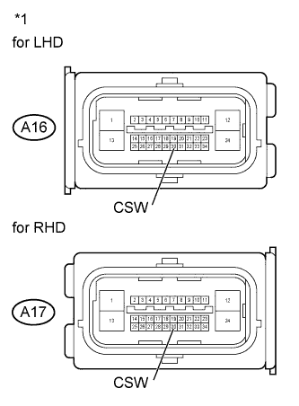
Text in illustration *1 Front view of wire harness connector
(to Skid Control ECU)
Disconnect the A16 or A17 skid control ECU connector.
-
Measure the resistance according to the value(s) in the table below.
Standard Resistance for LHD Tester Connection Switch Condition Specified Condition A16-30 (CSW) - Body ground VSC OFF Switch held ON Below 1 Ω A16-30 (CSW) - Body ground VSC OFF Switch OFF (Not pressed) 10 kΩ or higher for RHD Tester Connection Switch Condition Specified Condition A17-30 (CSW) - Body ground VSC OFF Switch held ON Below 1 Ω A17-30 (CSW) - Body ground VSC OFF Switch OFF (Not pressed) 10 kΩ or higher
NG 
INSPECT VSC OFF SWITCH Click here
OK
-
-
INSPECT COMBINATION METER ASSEMBLY
-
Reconnect the skid control ECU connector.
-
Connect the intelligent tester to the DLC3.
-
Perform Active Test of the combination meter using the intelligent tester Click here.
OK The VSC OFF indicator light turns ON or OFF in accordance with the intelligent tester.
NG
REPLACE COMBINATION METER ASSEMBLY Click here
OK 
REPLACE BRAKE ACTUATOR ASSEMBLY Click here
-
-
REPLACE COMBINATION METER ASSEMBLY
-
Turn the ignition switch off.
-
Replace the combination meter Click here.
NEXT
-
-
INSPECT COMBINATION METER ASSEMBLY
-
Connect the intelligent tester to the DLC3.
-
Perform Active Test of the combination meter using the intelligent tester Click here.
OK The VSC OFF indicator light turns ON or OFF in accordance with the intelligent tester.
NG
REPLACE BRAKE ACTUATOR ASSEMBLY Click here
OK
END
-
-
INSPECT VSC OFF SWITCH
-
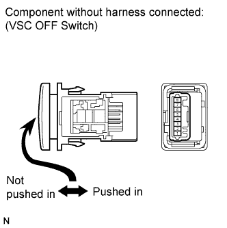
Disconnect the VSC OFF switch connector.
-
Measure the resistance according to the value(s) in the table below.
Standard Resistance Tester Connection Switch Condition Specified Condition 3 (E) - 6 (+) Switch is pushed in Below 1 Ω 3 (E) - 6 (+) Switch is not pushed in 10 kΩ or higher
NG
REPLACE VSC OFF SWITCH Click here
OK
-
-
CHECK HARNESS AND CONNECTOR (SKID CONTROL ECU - VSC OFF SWITCH)
-
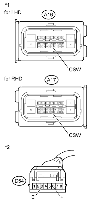
Text in illustration *1 Front view of wire harness connector
(to Skid Control ECU)
*2 Front view of wire harness connector
(to VSC OFF Switch)
Measure the resistance according to the value(s) in the table below.
Standard Resistance for LHD Tester Connection Condition Specified Condition A16-30 (CSW) - D54-6 (+) Always Below 1 Ω A16-30 (CSW) - Body ground Always 10 kΩ or higher D54-3 (E) - Body ground Always Below 1 Ω for RHD Tester Connection Condition Specified Condition A17-30 (CSW) - D54-6 (+) Always Below 1 Ω A17-30 (CSW) - Body ground Always 10 kΩ or higher D54-3 (E) - Body ground Always Below 1 Ω
NG
REPAIR OR REPLACE HARNESS OR CONNECTOR
OK
CHECK FOR INTERMITTENT PROBLEMS (SYMPTOM SIMULATION) Click here
-