VEHICLE STABILITY CONTROL SYSTEM TERMINALS OF ECU

-
TERMINALS OF ECU
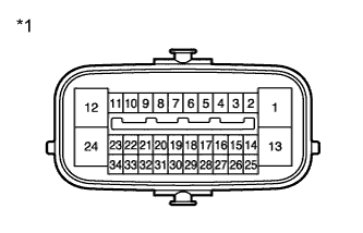
Text in Illustration *1 Component with out harness connected
(skid control ECU)
Terminal No. (Symbol) Terminal Description 1 (GND1) Skid control ECU ground 2 (STP) Stop light switch input 4 (RL-) Rear wheel speed LH (-) signal input 5 (RL+) Rear wheel speed LH (+) power supply output 6 (FR-) Front wheel speed RH (-) signal input 7 (FR+) Front wheel speed RH (+) power supply output 11 (SP1) Speed signal output for speedometer 12 (+BS) Solenoid relay power supply 13 (GND2) Pump motor ground 14 (CANL) CAN communication line L 16 (RR-) Rear wheel speed RH (-) signal input 17 (RR+) Rear wheel speed RH (+) power supply output 18 (FL-) Front wheel speed LH (-) signal input 19 (FL+) Front wheel speed LH (+) power supply output 24 (BM) Motor relay power supply 25 (CANH) CAN communication line H 30 (CSW) VSC OFF switch input 34 (IG1) ECU power supply -
TERMINAL INSPECTION
-
for LHD Models.
-
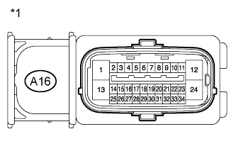
Text in Illustration *1 Front view of wire harness connector
(to skid control ECU)
Disconnect the connector and measure the voltage or resistance on the wire harness side.
Tech Tips
Voltage cannot be measured with the connector connected to the skid control ECU as the connector is watertight.
Standard Terminal No. (Symbol) Wiring Color Terminal Description Condition Specified Condition A16-1 (GND1) - Body ground W-B - Body ground Skid control ECU ground Always Below 1 Ω A16-2 (STP) - Body ground L-R - Body ground Stop light switch input Stop light switch ON → OFF
(Brake pedal depressed → released)
8 to 14 V
→ Below 1.5 V
A16-12 (+BS) - Body ground G - Body ground Solenoid relay power supply Always 11 to 14 V A16-13 (GND2) - Body ground W-B - Body ground Pump motor ground Always Below 1 Ω A16-24 (BM) - Body ground R - Body ground Motor relay power supply Always 11 to 14 V A16-25 (CANH) - A16-14 (CANL) B - W CAN bus Ignition switch off 54 to 69 Ω A16-30 (CSW) - Body ground V-W - Body ground VSC OFF switch input VSC OFF switch held ON → OFF (Not pressed) Below 25 Ω → 10 kΩ or higher A16-34 (IG1) - Body ground GR-R - Body ground ECU power supply Ignition switch ON 11 to 14 V
-
-
for RHD Models.
-
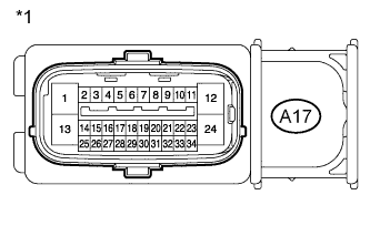
Text in Illustration *1 Front view of wire harness connector
(to skid control ECU)
Disconnect the connector and measure the voltage or resistance on the wire harness side.
Tech Tips
Voltage cannot be measured with the connector connected to the skid control ECU as the connector is watertight.
Standard Terminal No. (Symbol) Wiring Color Terminal Description Condition Specified Condition A17-1 (GND1) - Body ground W-B - Body ground Skid control ECU ground Always Below 1 Ω A17-2 (STP) - Body ground L-R - Body ground Stop light switch input Stop light switch ON → OFF
(Brake pedal depressed → released)
8 to 14 V
→ Below 1.5 V
A17-12 (+BS) - Body ground G - Body ground Solenoid relay power supply Always 11 to 14 V A17-13 (GND2) - Body ground W-B - Body ground Pump motor ground Always Below 1 Ω A17-24 (BM) - Body ground R - Body ground Motor relay power supply Always 11 to 14 V A17-25 (CANH) - A17-14 (CANL) B - W CAN bus Ignition switch off 54 to 69 Ω A17-30 (CSW) - Body ground V-W - Body ground VSC OFF switch input VSC OFF switch held ON → OFF (Not pressed) Below 25 Ω → 10 kΩ or higher A17-34 (IG1) - Body ground GR-R - Body ground ECU power supply Ignition switch ON 11 to 14 V
-
-