REAR AXLE BEAM INSTALLATION

-
INSTALL REAR AXLE CARRIER BUSH
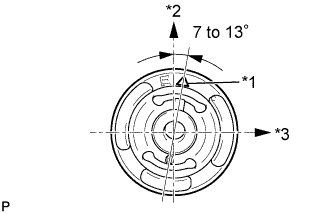
Text in Illustration *1 Bush Mark *2 Upper Side *3 Front Side
-
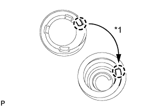
Align the matchmarks on a new bush and the axle beam and provisionally install the bush onto the rear axle beam, as shown in the illustration.
Note
Install the new bush in the same orientation as the old one was prior to removal, because they are directional.
-
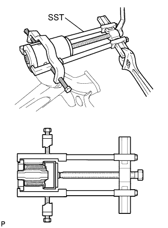
Using SST, install the bush onto the rear axle beam.
- SST
- 09950-40011 ( 09951-04020, 09952-04010, 09953-04030, 09954-04030, 09955-04051, 09957-04010, 09958-04011 )
- 09950-60020 ( 09951-00650 )
- 09726-40010
- 09570-22011
Note
Do not damage the rubber portion when installing the bush.
-
-
TEMPORARILY TIGHTEN REAR AXLE BEAM ASSEMBLY
-
Support the rear axle beam assembly with an engine lift.
-
Install the rear axle beam assembly onto the vehicle and provisionally tighten the 2 bolts.
-
-
INSTALL REAR COIL SPRING
-
Install the coil spring insulator lower onto the rear axle beam.
-
Text in Illustration *1 Fit Install the coil spring insulator upper so that its gap fits onto the end of coil spring.
-
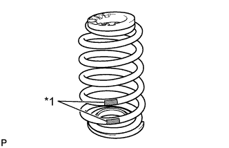
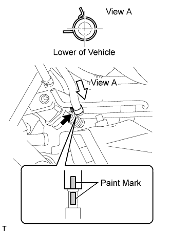
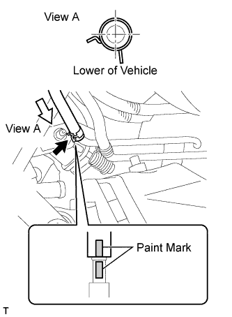
Text in Illustration *1 Paint Mark Install the coil spring onto the rear axle beam.
Note
The paint mark of the coil spring should be towards the underside and rear side of the vehicle.
-
-
TEMPORARILY TIGHTEN REAR SHOCK ABSORBER ASSEMBLY
-
Support the axle beam with a jack. Insert a wooden block between the jack and the rear axle spring seat to prevent damage.
-
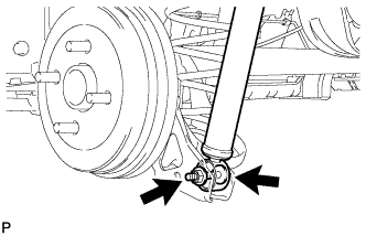
Jack up the axle beam slowly, and provisionally install the shock absorber (lower side) with the bolt and nut onto the axle beam.
-
Install the suspension support and cushion retainer.
-
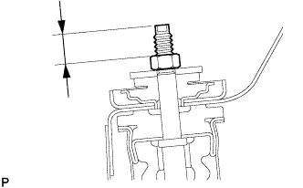
While holding the piston rod, install a new nut (lower nut) to the specified standard.
Standard 15 to 18 mm (0.591 to 0.709 in.) -
Install a new nut (upper nut) onto the lower nut.
-
Hold the lower nut and tighten the upper nut against it.
- Torque:
- 25 N*m { 250 kgf*cm, 18 ft.*lbf }
-
-
INSTALL REAR FLOOR PANEL BRACE LH
-
Install the rear floor panel brace LH with the 2 bolts.
- Torque:
- 30 N*m { 307 kgf*cm, 22 ft.*lbf }
-
-
INSTALL REAR FLOOR PANEL BRACE RH
Tech Tips
Use the same procedure for the RH side as for the LH side.
-
INSTALL REAR AXLE HUB AND BEARING ASSEMBLY (for Rear Drum Brake)
-
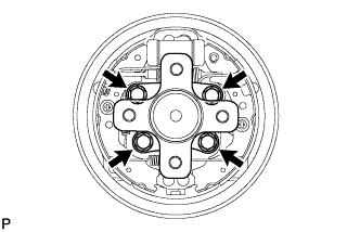
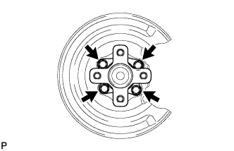
Install the rear axle hub and bearing assembly with the 4 bolts.
- Torque:
- 90 N*m { 918 kgf*cm, 66 ft.*lbf }
-
-
INSPECT REAR AXLE HUB BEARING LOOSENESS (for Rear Drum Brake)
-
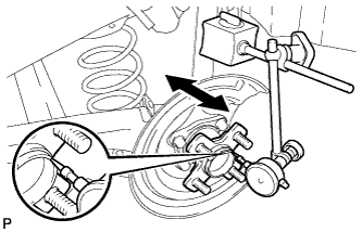
Using a dial indicator, check for looseness near the center of the axle hub.
Maximum looseness 0.05 mm (0.00197 in.) Tech Tips
-
Ensure that the dial indicator is set perpendicular to the measurement surface.
-
If the looseness exceeds the maximum, replace the rear axle hub and bearing assembly.
-
-
-
INSPECT REAR AXLE HUB RUNOUT (for Rear Drum Brake)
-
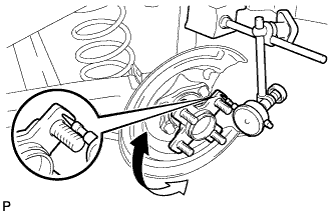
Using a dial indicator, check for runout on the surface of the axle hub outside the hub bolt.
Maximum runout 0.07 mm (0.00276 in.) Tech Tips
-
Ensure that the dial indicator is set perpendicular to the measurement surface.
-
If the runout exceeds the maximum, replace the rear axle hub and bearing assembly.
-
-
-
INSTALL REAR BRAKE DRUM (for Rear Drum Brake)
-
INSTALL REAR DISC BRAKE DUST COVER SUB-ASSEMBLY LH (for Rear Disc Brake)
-
INSTALL REAR DISC BRAKE DUST COVER SUB-ASSEMBLY RH (for Rear Disc Brake)
Tech Tips
Use the same procedure for the RH side as for the LH side.
-
INSTALL REAR AXLE HUB AND BEARING ASSEMBLY (for Rear Disc Brake)
-
Install the rear axle hub and bearing assembly with the 4 bolts.
- Torque:
- 90 N*m { 918 kgf*cm, 66 ft.*lbf }
-
-
INSPECT REAR AXLE HUB BEARING LOOSENESS (for Rear Disc Brake)
-
Using a dial indicator, check for looseness near the center of the axle hub.
Maximum looseness 0.05 mm (0.00197 in.) Tech Tips
-
Ensure that the dial indicator is set perpendicular to the measurement surface.
-
If the looseness exceeds the maximum, replace the rear axle hub and bearing assembly.
-
-
-
INSPECT REAR AXLE HUB RUNOUT (for Rear Disc Brake)
-
Using a dial indicator, check for runout on the surface of the axle hub outside the hub bolt.
Maximum runout 0.07 mm (0.00276 in.) Tech Tips
-
Ensure that the dial indicator is set perpendicular to the measurement surface.
-
If the runout exceeds the maximum, replace the rear axle hub and bearing assembly.
-
-
-
INSTALL REAR DISC (for Rear Disc Brake)
-
INSTALL REAR DISC BRAKE CYLINDER MOUNTING LH (for Rear Disc Brake)
-
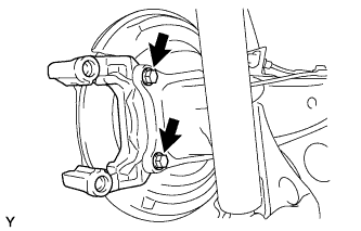
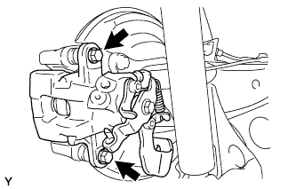
Install the rear disc brake cylinder mounting to the axle beam with the 2 bolts.
- Torque:
- 57 N*m { 585 kgf*cm, 42 ft.*lbf }
-
-
INSTALL REAR DISC BRAKE CYLINDER MOUNTING RH (for Rear Disc Brake)
Tech Tips
Use the same procedure for the RH side as for the LH side.
-
INSTALL REAR DISC BRAKE PAD LH (for Rear Disc Brake)
-
Install the 2 rear disc brake pads to the rear disc brake cylinder mounting.
Note
There should be no oil or grease on the friction surfaces of the disc brake pads or the rear disc.
-
-
INSTALL REAR DISC BRAKE PAD RH (for Rear Disc Brake)
Tech Tips
Use the same procedure for the RH side as for the LH side.
-
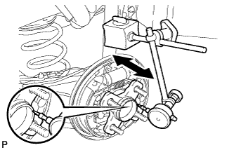
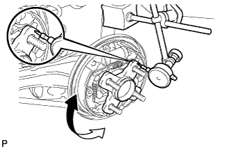
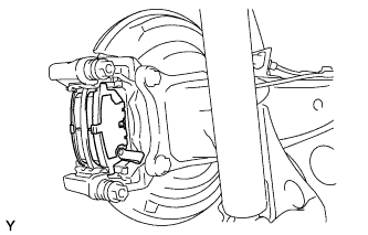
INSTALL REAR DISC BRAKE CYLINDER ASSEMBLY LH (for Rear Disc Brake)
-
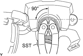
To compensate for pad wear when reusing the pad, use SST to push and turn the piston (LH side: counterclockwise, RH side: clockwise) to the position where the protrusion on the pad lines up properly with the piston groove.
- SST
- 09960-10010 ( 09963-00400 )
Note
Place the disc between the 2 brake pads and determine the piston return value.
-
Hold the rear disc brake pad guide pin, and install the rear disc brake cylinder assembly to the rear disc brake cylinder mounting with the 2 bolts.
- Torque:
- 34 N*m { 350 kgf*cm, 25 ft.*lbf }
-
-
INSTALL REAR DISC BRAKE CYLINDER ASSEMBLY RH (for Rear Disc Brake)
Tech Tips
Use the same procedure for the RH side as for the LH side.
-
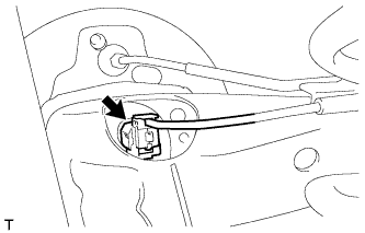
INSTALL PARKING BRAKE NO. 3 CABLE ASSEMBLY
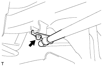
-
Install the parking brake cable with the bolt.
- Torque:
- 6.0 N*m { 61 kgf*cm, 53 in.*lbf }
-
-
INSTALL PARKING BRAKE NO. 2 CABLE ASSEMBLY
Tech Tips
Use the same procedure for the RH side as for the LH side.
-
INSTALL REAR BRAKE NO. 4 TUBE (for Rear Drum Brake)
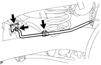
-
Install the brake tube onto the axle beam with the nut.
- Torque:
- 8.5 N*m { 87 kgf*cm, 75 in.*lbf }
-
Connect the flexible hose to the axle beam with a new clip.
-
Using a union nut wrench, install the brake tube onto the flexible hose.
- Torque:
- 15 N*m { 155 kgf*cm, 11 ft.*lbf }
Note
Use the formula to calculate special torque values for situations where a union nut wrench is combined with a torque wrench Click here.
-
-
INSTALL REAR BRAKE NO. 3 TUBE (for Rear Drum Brake)
Tech Tips
Use the same procedure for the RH side as for the LH side.
-
INSTALL REAR BRAKE NO. 4 TUBE (for Rear Disc Brake)
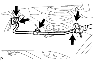
-
Install the brake tube onto the axle beam with the nut.
- Torque:
- 8.5 N*m { 87 kgf*cm, 75 in.*lbf }
-
Connect the 2 flexible hoses to the axle beam with 2 new clips.
-
Using a union nut wrench, install the brake tube onto the flexible hose.
- Torque:
- 15 N*m { 155 kgf*cm, 11 ft.*lbf }
Note
Use the formula to calculate special torque values for situations where a union nut wrench is combined with a torque wrench Click here.
-
-
INSTALL REAR BRAKE NO. 3 TUBE (for Rear Disc Brake)
Tech Tips
Use the same procedure for the RH side as for the LH side.
-
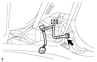
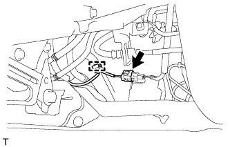
INSTALL SKID CONTROL SENSOR WIRE
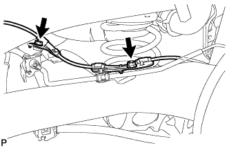
-
Install the skid control sensor wire onto the axle beam with the bolt and the nut.
- Torque:
- 8.5 N*m { 87 kgf*cm, 75 in.*lbf }
-
Connect the skid control sensor wire connector.
-
-
INSTALL TAIL EXHAUST PIPE ASSEMBLY (for 1KR-FE)
-
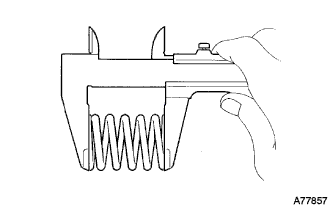
Using a vernier caliper, measure the free length of the compression springs.
Minimum Length Item Length Rear 38.5 mm (1.594 in.) Tech Tips
If the length is not as specified, replace the compression spring.
-
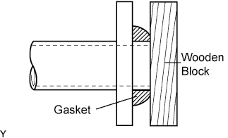
Using a hammer and a wooden block, tap in the gasket until its surface is flush with the front exhaust pipe assembly.
Note
-
Install the gasket in the correct direction.
-
Do not reuse the gasket.
-
Do not damage the gasket by dropping it, etc
-
Do not damage the outer surface of the gasket.
-
Do not push in the gasket with the exhaust pipe when connecting it.
-
After the installation, check that the gaps between the flanges of the front exhaust pipe assembly and tail exhaust pipe assembly are consistent front-to-rear and left-to-right
-
-
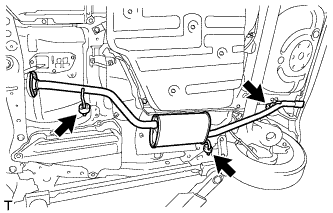
Hang the tail exhaust pipe assembly with the 3 exhaust pipe supports.
-
Install the tail exhaust pipe assembly to the front exhaust assembly with the 2 bolts and the 2 compression springs.
- Torque:
- 43 N*m { 438 kgf*cm, 32 ft.*lbf }
-
-
INSTALL TAIL EXHAUST PIPE ASSEMBLY (for 1NR-FE)
-
Using a vernier caliper, measure the free length of the compression springs.
Minimum Length Item Length Rear 38.5 mm (1.594 in.) Tech Tips
If the length is not as specified, replace the compression spring.
-
Fully push a new exhaust pipe gasket onto the front exhaust pipe assembly.
Note
-
Install the gasket in the correct direction.
-
Do not reuse the gasket.
-
Do not damage the gasket by dropping it, etc
-
Do not damage the outer surface of the gasket.
-
Do not push in the gasket with the exhaust pipe when connecting it.
-
After the installation, check that the gaps between the flanges of the front exhaust pipe assembly and tail exhaust pipe assembly are consistent front-to-rear and left-to-right
-
-
Hang the tail exhaust pipe assembly with the 3 exhaust pipe supports.
-
Install the tail exhaust pipe assembly to the front exhaust assembly with the 2 bolts and the 2 compression springs.
- Torque:
- 43 N*m { 438 kgf*cm, 32 ft.*lbf }
-
-
INSTALL TAIL EXHAUST PIPE ASSEMBLY (for 1ND-TV without DPF)
-
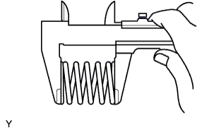
Using a vernier caliper, measure the free length of the compression spring.
Minimum length 41.5 mm (1.634 in.) If the length is not as specified, replace the compression spring.
-

Using a plastic hammer and a wooden block, tap in a new gasket until its surface is flush with the exhaust manifold.
Note
-
Install the exhaust pipe gasket in the correct direction.
-
Do not damage the outer surface of the exhaust pipe gasket.
-
Do not reuse the exhaust pipe gasket.
-
Do not push in the gasket with the exhaust pipe when connecting it.
-
-
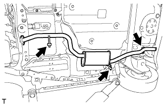
Hang the tail exhaust pipe assembly with the 3 No. 4 exhaust pipe supports.
-
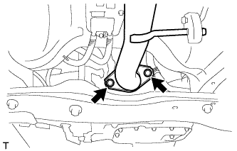
Install the tail exhaust pipe assembly with the 2 compression springs and 2 bolts.
- Torque:
- 43 N*m { 438 kgf*cm, 32 ft.*lbf }
-
-
INSTALL TAIL EXHAUST PIPE ASSEMBLY (for 1ND-TV with DPF)
-
Using a vernier caliper, measure the free length of the compression spring.
Minimum length 41.5 mm (1.634 in.) If the length is not as specified, replace the compression spring.
-
Using a plastic hammer and a wooden block, tap in a new gasket until its surface is flush with the exhaust manifold.
Note
-
Install the exhaust pipe gasket in the correct direction.
-
Do not damage the outer surface of the exhaust pipe gasket.
-
Do not reuse the exhaust pipe gasket.
-
Do not push in the gasket with the exhaust pipe when connecting it.
-
-
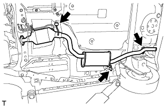
Hang the tail exhaust pipe assembly with the 3 No. 4 exhaust pipe supports.
-
Install the tail exhaust pipe assembly with the 2 compression springs and 2 bolts.
- Torque:
- 43 N*m { 438 kgf*cm, 32 ft.*lbf }
-
-
INSTALL NO. 8 EXHAUST PIPE AIR HOSE (for 1ND-TV with DPF)
-
Connect the No. 8 air hose to the tail exhaust pipe.
-
-
INSTALL NO. 7 EXHAUST PIPE AIR HOSE (for 1ND-TV with DPF)
-
Connect the No. 7 air hose to the tail exhaust pipe.
-
-
INSTALL NO. 2 EXHAUST GAS TEMPERATURE SENSOR (for 1ND-TV with DPF)
-
Using a union nut wrench (14 mm), install the No. 2 exhaust gas temperature sensor.
- Torque:
- 30 N*m { 306 kgf*cm, 22 ft.*lbf }
Note
Use the formula to calculate special torque values for situations where a union nut wrench is combined with a torque wrench Click here.
-
Engage the harness clamp.
-
Engage the harness clamp and connect the No. 2 exhaust gas temperature sensor connector.
-
-
INSTALL ENGINE UNDER COVER (for 1ND-TV with DPF)
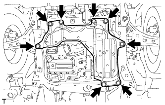
-
Install the engine under cover assembly with the 4 bolts and the 4 clips.
- Torque:
- 5.0 N*m { 51 kgf*cm, 44 in.*lbf }
-
-
INSTALL REAR WHEEL
- Torque:
- 103 N*m { 1,050 kgf*cm, 76 ft.*lbf }
-
STABILIZE SUSPENSION
-
Lower the vehicle from the jack.
-
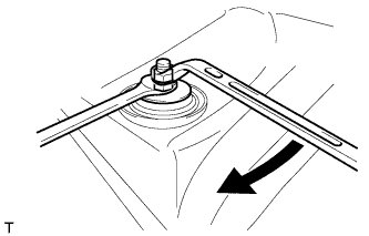
Bounce the vehicle up and down several times to stabilize the suspension.
-
-
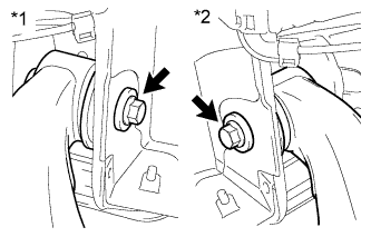
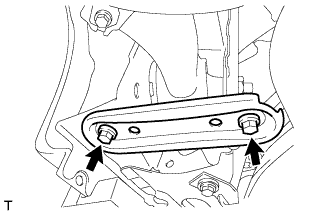
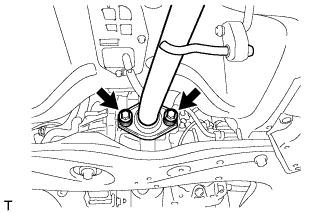
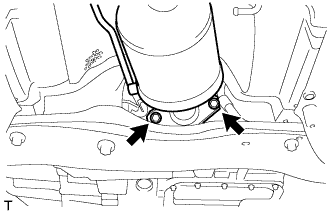
FULLY TIGHTEN REAR AXLE BEAM ASSEMBLY
Text in Illustration *1 RH Side *2 LH Side
-
Fully tighten the 2 bolts.
- Torque:
- 90 N*m { 918 kgf*cm, 67 ft.*lbf }
-
-
FULLY TIGHTEN REAR SHOCK ABSORBER ASSEMBLY
-
Fully tighten the shock absorber (lower side) with the bolt.
- Torque:
- 49 N*m { 500 kgf*cm, 36 ft.*lbf }
-
-
BLEED BRAKE SYSTEM
Tech Tips
Refer to the instructions for bleed brake line Click here.
-
INSPECT FOR EXHAUST GAS LEAK
-
INSPECT REAR WHEEL ALIGNMENT
-
CHECK FOR SPEED SENSOR SIGNAL