REAR AXLE BEAM REMOVAL

CAUTION:
When the rear axle beam assembly is removed, the front-to-rear weight balance of the raised vehicle becomes unstable, creating the danger that the vehicle might fall. Therefore, before removing the rear axle beam assembly, securely support the front suspension cross member with a transmission jack or other suitable lift.
-
REMOVE REAR WHEEL
-
DRAIN BRAKE FLUID
Note
Immediately wash off any brake fluid that comes into contact with any painted surfaces.
-
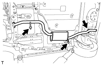
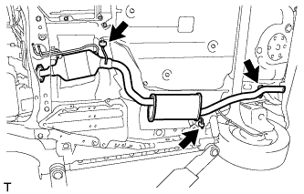
REMOVE TAIL EXHAUST PIPE ASSEMBLY (for 1KR-FE)
-
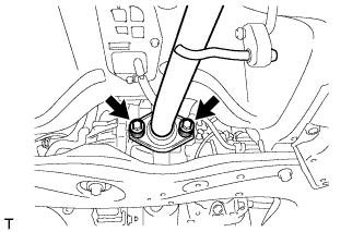
Remove the 2 bolts and the 2 compression springs, and separate the front exhaust pipe assembly from the tail exhaust pipe assembly.
-
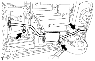
Remove the 3 exhaust pipe supports and the tail exhaust pipe assembly.
-
-
REMOVE TAIL EXHAUST PIPE ASSEMBLY (for 1NR-FE)
-
Remove the 2 bolts and the 2 compression springs, and separate the tail exhaust pipe assembly from the front exhaust pipe assembly.
-
Remove the 3 exhaust pipe supports and the tail exhaust pipe assembly.
-
-
REMOVE TAIL EXHAUST PIPE ASSEMBLY (for 1ND-TV without DPF)
-
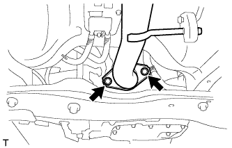
Remove the 2 bolts and 2 compression springs.
-
Remove the 3 No. 4 exhaust pipe supports and remove the tail exhaust pipe assembly.
-
-
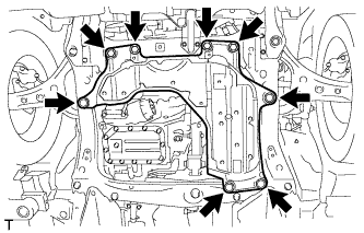
REMOVE ENGINE UNDER COVER (for 1ND-TV with DPF)
-
Remove the 4 bolts, 4 clips and the engine under cover.
-
-
REMOVE NO. 2 EXHAUST GAS TEMPERATURE SENSOR (for 1ND-TV with DPF)
-
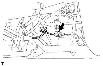
Disconnect the No. 2 exhaust gas temperature sensor connector and disengage the harness clamp.
-
Disengage the harness clamp.
-
Using a union nut wrench (14 mm), remove the No. 2 exhaust gas temperature sensor.
-
-
REMOVE TAIL EXHAUST PIPE ASSEMBLY (for 1ND-TV with DPF)
-
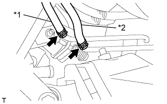
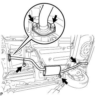
*1 No. 7 Air hose *2 No. 8 Air hose Disconnect the 2 air hoses.
-
Remove the 2 bolts and 2 compression springs.
-
Remove the 3 No. 4 exhaust pipe supports and remove the tail exhaust pipe assembly.
-
-
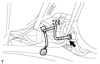
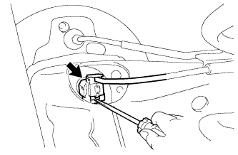
SEPARATE SKID CONTROL SENSOR WIRE
-
Using a screwdriver, remove the claw of the connector lock and disconnect the skid control sensor wire connector.
Note
Do not remove the connector cover from the connector because the skid control sensor wire may be damaged.
-
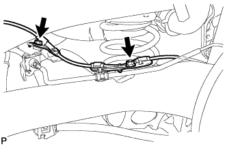
Remove the bolt and the nut, and separate the skid control sensor wire.
-
-
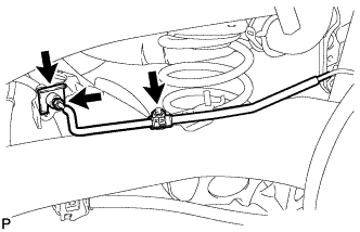
SEPARATE REAR BRAKE NO. 4 TUBE (for Rear Drum Brake)
-
Using a union nut wrench, separate the brake tube from the flexible hose.
-
Remove the clip and disconnect the flexible hose from the axle beam.
-
Remove the nut and separate the brake tube.
-
-
SEPARATE REAR BRAKE NO. 3 TUBE (for Rear Drum Brake)
Tech Tips
Use the same procedure for the RH side as for the LH side.
-
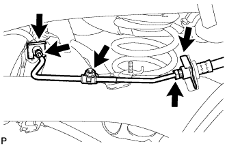
REMOVE REAR BRAKE NO. 4 TUBE (for Rear Disc Brake)
-
Using a union nut wrench, separate the brake tube from the flexible hose.
-
Remove the 2 clips and disconnect the 2 flexible hoses from the axle beam.
-
Remove the nut and remove the brake tube.
-
-
REMOVE REAR BRAKE NO. 3 TUBE (for Rear Disc Brake)
Tech Tips
Use the same procedure for the RH side as for the LH side.
-
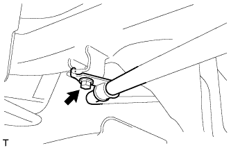
SEPARATE PARKING BRAKE NO. 3 CABLE ASSEMBLY
-
Remove the bolt and separate the parking brake cable.
-
-
SEPARATE PARKING BRAKE NO. 2 CABLE ASSEMBLY
Tech Tips
Use the same procedure for the RH side as for the LH side.
-
REMOVE REAR BRAKE DRUM (for Rear Drum Brake)
-
REMOVE REAR AXLE HUB AND BEARING ASSEMBLY (for Rear Drum Brake)
-
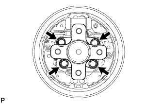
Remove the 4 bolts and the rear axle hub and bearing assembly.
-
-
SEPARATE REAR DISC BRAKE CYLINDER ASSEMBLY LH (for Rear Disc Brake)
-
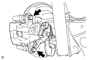
Hold the rear disc brake pad guide pin and remove the 2 bolts and rear disc brake cylinder assembly.
-
-
SEPARATE REAR DISC BRAKE CYLINDER ASSEMBLY RH (for Rear Disc Brake)
Tech Tips
Use the same procedure for the RH side as for the LH side.
-
REMOVE REAR DISC BRAKE PAD LH (for Rear Disc Brake)
-
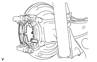
Remove the 2 disc brake pads from the rear disc brake cylinder mounting.
-
-
REMOVE REAR DISC BRAKE PAD RH (for Rear Disc Brake)
Tech Tips
Use the same procedure for the RH side as for the LH side.
-
REMOVE REAR DISC BRAKE CYLINDER MOUNTING LH (for Rear Disc Brake)
-
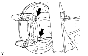
Remove the 2 bolts and the rear disc brake cylinder mounting from the axle beam.
-
-
REMOVE REAR DISC BRAKE CYLINDER MOUNTING RH (for Rear Disc Brake)
Tech Tips
Use the same procedure for the RH side as for the LH side.
-
REMOVE REAR DISC (for Rear Disc Brake)
-
REMOVE REAR AXLE HUB AND BEARING ASSEMBLY (for Rear Disc Brake)
-
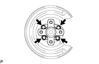
Remove the 4 bolts and the rear axle hub and bearing assembly.
-
-
REMOVE REAR DISC BRAKE DUST COVER SUB-ASSEMBLY LH (for Rear Disc Brake)
-
REMOVE REAR DISC BRAKE DUST COVER SUB-ASSEMBLY RH (for Rear Disc Brake)
Tech Tips
Use the same procedure for the RH side as for the LH side.
-
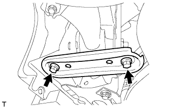
REMOVE REAR FLOOR PANEL BRACE LH
-
Remove the 2 bolts and the rear floor panel brace LH.
-
-
REMOVE REAR FLOOR PANEL BRACE RH
Tech Tips
Use the same procedure for the RH side as for the LH side.
-
LOOSEN REAR AXLE BEAM ASSEMBLY
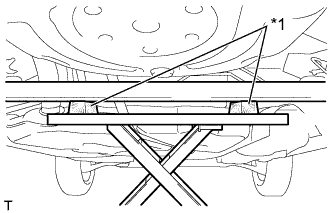
Text in Illustration *1 Wooden Blocks
-
Support the rear axle beam assembly using an engine lift and 2 wooden blocks as shown in the illustration.
CAUTION:
Securely support the rear axle beam assembly to prevent it from falling.
-
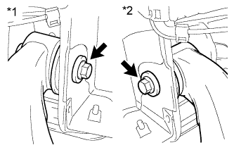
Text in Illustration *1 RH Side *2 LH Side Loosen the 2 bolts.
Note
Do not remove the bolts.
-
-
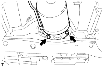
REMOVE REAR SHOCK ABSORBER ASSEMBLY
-
Support the axle beam with a jack. Insert a wooden block between the jack and the rear axle spring seat to prevent damage.
-
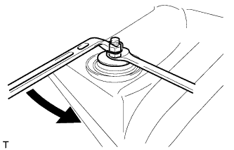
Hold the lower nut and loosen the upper nut.
-
Remove the 2 nuts.
-
Remove the cushion retainer and suspension support.
-
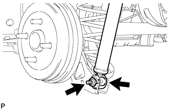
Remove the bolt while keeping the nut from rotating and remove the shock absorber.
Note
Remove the nut from the bolt side because the nut is a jam nut.
-
-
REMOVE REAR COIL SPRING
-
Lower the engine lift slowly.
-
Remove the coil spring, coil spring insulator upper and coil spring insulator lower.
-
-
REMOVE REAR AXLE BEAM ASSEMBLY
-
Text in Illustration *1 RH Side *2 LH Side Remove the 2 bolts and remove the rear axle beam assembly.
-
-
REMOVE REAR AXLE CARRIER BUSH
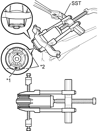
Text in Illustration *1 Bush Mark *2 Bush Rib
-
Place a matchmark on the rear axle beam with it aligned with the bush mark.
-
Using a chisel and hammer, bend the 2 portions of the bush rib.
Note
-
Bend the bush rib until the claw of SST can be suspended.
-
When removing the bush, do not rub off the matchmark on the rear axle beam
-
-
Using SST, remove the bush from the rear axle beam.
- SST
- 09950-40011 ( 09951-04020, 09952-04010, 09953-04030, 09954-04020, 09955-04011, 09957-04010, 09958-04011 )
- 09950-60010 ( 09951-00470 )
- 09710-30012 ( 09710-04061 )
Note
Apply paint to any scratches on the rear axle beam.
-