REAR COIL SPRING REMOVAL

-
REMOVE REAR WHEEL
-
DRAIN BRAKE FLUID
Note
Immediately wash off any brake fluid that comes into contact with any painted surfaces.
-
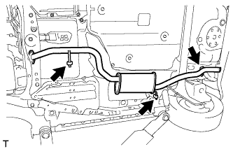
REMOVE TAIL EXHAUST PIPE ASSEMBLY (for 1KR-FE)
-
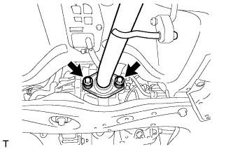
Remove the 2 bolts and the 2 compression springs, and separate the front exhaust pipe assembly from the tail exhaust pipe assembly.
-
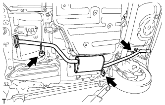
Remove the 3 exhaust pipe supports and the tail exhaust pipe assembly.
-
-
REMOVE TAIL EXHAUST PIPE ASSEMBLY (for 1NR-FE)
-
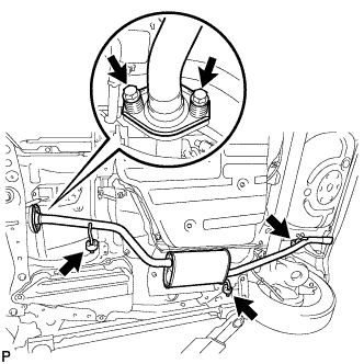
Remove the 2 bolts and the 2 compression springs, and separate the tail exhaust pipe assembly from the front exhaust pipe assembly.
-
Remove the 3 exhaust pipe supports and the tail exhaust pipe assembly.
-
-
REMOVE TAIL EXHAUST PIPE ASSEMBLY (for 1ND-TV without DPF)
-
Remove the 2 bolts and 2 compression springs.
-
Remove the 3 No. 4 exhaust pipe supports and remove the tail exhaust pipe assembly.
-
-
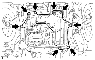
REMOVE ENGINE UNDER COVER (for 1ND-TV with DPF)
-
Remove the 4 bolts, 4 clips and the engine under cover.
-
-
REMOVE NO. 2 EXHAUST GAS TEMPERATURE SENSOR (for 1ND-TV with DPF)
-
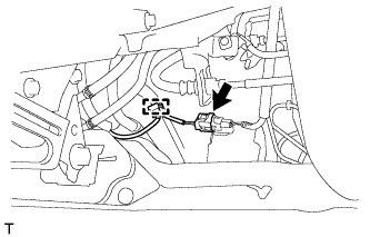
Disconnect the No. 2 exhaust gas temperature sensor connector and disengage the harness clamp.
-
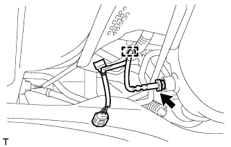
Disengage the harness clamp.
-
Using a union nut wrench (14 mm), remove the No. 2 exhaust gas temperature sensor.
-
-
REMOVE TAIL EXHAUST PIPE ASSEMBLY (for 1ND-TV with DPF)
-
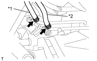
*1 No. 7 Air hose *2 No. 8 Air hose Disconnect the 2 air hoses.
-
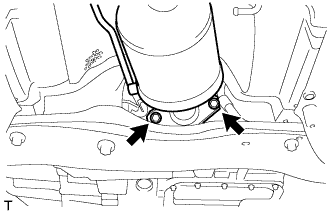
Remove the 2 bolts and 2 compression springs.
-
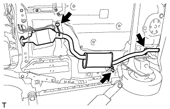
Remove the 3 No. 4 exhaust pipe supports and remove the tail exhaust pipe assembly.
-
-
SEPARATE SKID CONTROL SENSOR WIRE
-
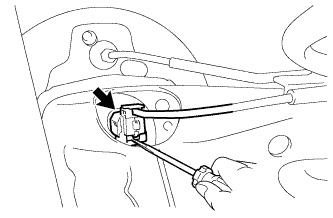
Using a screwdriver, remove the claw of the connector lock and disconnect the skid control sensor wire connector.
Note
Do not remove the connector cover from the connector because the skid control sensor wire may be damaged.
-
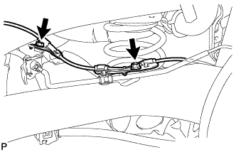
Remove the bolt and the nut, and separate the skid control sensor wire.
-
-
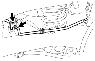
SEPARATE REAR FLEXIBLE HOSE LH
-
Using a union nut wrench, separate the brake tube from the flexible hose.
-
Remove the clip and disconnect the flexible hose from the axle beam.
-
-
SEPARATE REAR FLEXIBLE HOSE RH
Tech Tips
Use the same procedure for the RH side as for the LH side.
-
REMOVE REAR FLOOR PANEL BRACE LH
-
Remove the 2 bolts and the rear floor panel brace LH.
-
-
REMOVE REAR FLOOR PANEL BRACE RH
Tech Tips
Use the same procedure for the RH side as for the LH side.
-
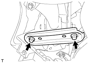
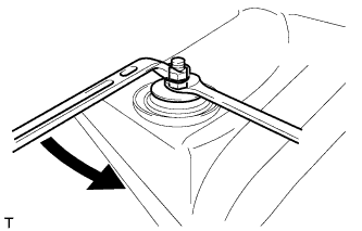
LOOSEN REAR AXLE BEAM ASSEMBLY
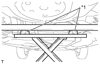
Text in Illustration *1 Wooden Block
-
Support the rear axle beam assembly using an engine lift and 2 wooden blocks as shown in the illustration.
-
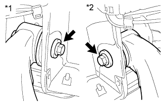
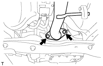
Text in Illustration *1 RH Side *2 LH Side Loosen the 2 bolts.
Note
Do not remove the bolts.
-
-
REMOVE REAR SHOCK ABSORBER ASSEMBLY
-
Support the axle beam with a jack. Insert a wooden block between the jack and the rear axle spring seat to prevent damage.
-
Hold the lower nut and loosen the upper nut.
-
Remove the 2 nuts.
-
Remove the cushion retainer and suspension support.
-
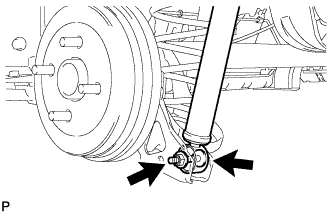
Remove the bolt while keeping the nut from rotating and remove the shock absorber.
Note
Remove the nut from the bolt side because the nut is a jam nut.
-
-
REMOVE REAR COIL SPRING
-
Lower the engine lift slowly.
-
Remove the coil spring, coil spring insulator upper and coil spring insulator lower.
-