REAR AXLE HUB ON-VEHICLE INSPECTION

Tech Tips
-
Use the same procedure for the RH side and LH side.
-
The procedure listed below is for the LH side.
-
REMOVE SHIFT LEVER KNOB SUB-ASSEMBLY (for Manual Transaxle with Rear Disc Brake)
-
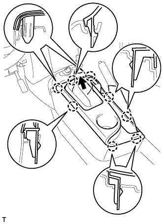
REMOVE CONSOLE UPPER PANEL SUB-ASSEMBLY (for Manual Transaxle with Rear Disc Brake)
-
Disengage the 8 claws and remove the console upper panel.
-
Separate the shifting hole cover.
-
-
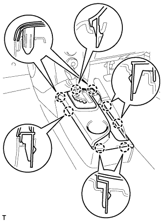
REMOVE CONSOLE UPPER PANEL SUB-ASSEMBLY (for CVT with Rear Disc Brake)
-
Disengage the 8 claws and remove the console upper panel.
-
-
LOOSEN ADJUSTING NUT (for Rear Disc Brake)
-
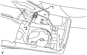
Text in Illustration *1 Lock Nut *2 Adjusting Nut Loosen the lock nut and adjusting nu to completely release the No. 1 parking brake cable assembly.
-
-
REMOVE REAR WHEEL
-
SEPARATE NO. 3 PARKING BRAKE CABLE ASSEMBLY (for Rear Disc Brake)
-
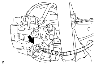
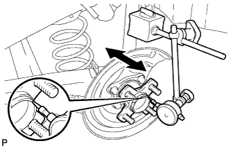
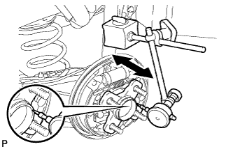
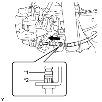
Separate the No. 3 parking brake cable assembly from the rear disc brake cylinder operation lever.
-
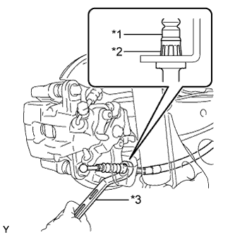
Text in Illustration *1 No. 3 Parking Brake Cable Assembly *2 Clip *3 Offset Wrench (14 mm) Insert an offset wrench (14 mm) at the base of the parking brake cable as shown in the illustration to disengage the clip. Pull out the parking brake cable from the rear disc brake cylinder assembly.
-
-
SEPARATE REAR DISC BRAKE CALIPER ASSEMBLY (for Rear Disc Brake)
-
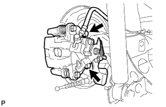
Remove the 2 bolts, and separate the rear disc brake caliper assembly.
Note
Use wire or an equivalent tool to keep the brake caliper from hanging down by the flexible hose.
-
-
REMOVE REAR DISC (for Rear Disc Brake)
-
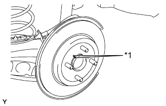
Text in Illustration *1 Matchmark Place matchmarks on the disc and axle hub and remove the disc.
-
-
REMOVE REAR BRAKE DRUM (for Rear Drum Brake)
-
Text in Illustration *1 Automatic Adjust Lever Release the parking brake and remove the rear brake drum.
Tech Tips
If the rear brake drum cannot be removed easily, perform the following procedure.
-
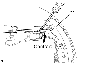
Remove the shoe adjusting hole plug and insert a screwdriver through the hole into the backing plate, and hold the automatic adjust lever away from the adjuster.
-
Using another screwdriver, contract the brake shoe by turning the adjusting bolt.
-
-
-
INSPECT REAR AXLE HUB BEARING LOOSENESS (for Rear Disc Brake)
-
Using a dial indicator, check for looseness near the center of the axle hub.
Maximum looseness 0.05 mm (0.00197 in.) Tech Tips
-
Ensure that the dial indicator is set perpendicular to the measurement surface.
-
If the looseness exceeds the maximum, replace the rear axle hub and bearing assembly.
-
-
-
INSPECT REAR AXLE HUB RUNOUT (for Rear Disc Brake)
-
Using a dial indicator, check for runout on the surface of the axle hub outside the hub bolt.
Maximum runout 0.07 mm (0.00276 in.) Tech Tips
-
Ensure that the dial indicator is set perpendicular to the measurement surface.
-
If the runout exceeds the maximum, replace the rear axle hub and bearing assembly.
-
-
-
INSPECT REAR AXLE HUB BEARING LOOSENESS (for Rear Drum Brake)
-
Using a dial indicator, check for looseness near the center of the axle hub.
Maximum looseness 0.05 mm (0.00197 in.) Tech Tips
-
Ensure that the dial indicator is set perpendicular to the measurement surface.
-
If the looseness exceeds the maximum, replace the rear axle hub and bearing assembly.
-
-
-
INSPECT REAR AXLE HUB RUNOUT (for Rear Drum Brake)
-
Using a dial indicator, check for runout on the surface of the axle hub outside the hub bolt.
Maximum runout 0.07 mm (0.00276 in.) Tech Tips
-
Ensure that the dial indicator is set perpendicular to the measurement surface.
-
If the runout exceeds the maximum, replace the rear axle hub and bearing assembly.
-
-
-
INSTALL REAR DISC (for Rear Disc Brake)
-
Text in Illustration *1 Matchmark Align the matchmarks of the disc and axle hub and install the disc.
Note
When replacing the disc with a new one, select the installation position where the rear disc has minimal runout.
-
-
INSTALL REAR BRAKE DRUM (for Rear Drum Brake)
-
INSTALL REAR DISC BRAKE CALIPER ASSEMBLY (for Rear Disc Brake)
-
Install the rear disc brake caliper assembly with the 2 bolts.
- Torque:
- 57 N*m { 585 kgf*cm, 42 ft.*lbf }
-
-
CONNECT NO. 3 PARKING BRAKE CABLE ASSEMBLY (for Rear Disc Brake)
-
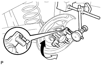
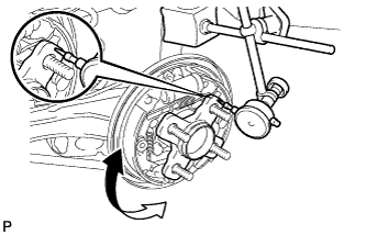
Text in Illustration *1 No. 3 Parking Brake Cable Assembly *2 Clip Insert the parking brake cable into the disc brake cylinder and engage the clip claws of the parking brake cable to the rear disc brake cylinder guide as shown in the illustration.
-
Connect the cable end to the rear disc brake cylinder operation lever.
-
-
TEMPORARILY TIGHTEN ADJUSTING NUT (for Rear Disc Brake)
-
Text in Illustration *1 Lock Nut *2 Adjusting Nut Temporarily install the adjusting nut and the lock nut to the No. 1 parking brake cable assembly.
-
-
ADJUST PARKING BRAKE LEVER TRAVEL (for Rear Disc Brake)
-
Completely release the parking brake lever.
-
Text in Illustration *1 Lock Nut *2 Adjusting Nut Loosen the lock nut and the adjusting nut to completely release the parking brake cable.
-
Fully depress the brake pedal 3 to 5 times with the engine stopped.
-
Turn the adjusting nut until the parking brake lever travel is corrected to within the specified range.
Parking brake lever travel at 200 N (20 kgf, 45.0 lbf) Rear Brake Type Number of Clicks Disc 5 to 8 Drum 6 to 9 -
Using a wrench or an equivalent tool, hold the adjusting nut and tighten the lock nut.
- Torque:
- 6.0 N*m { 61 kgf*cm, 53 in.*lbf }
-
Operate the parking brake lever 3 to 4 times, and check the parking brake lever travel.
-
Check whether the parking brake drags or not.
-
-
INSPECT REAR DISC BRAKE CYLINDER OPERATION LEVER AND STOPPER CLEARANCE (for Rear Disc Brake)
-
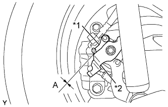
Text in Illustration *1 Stopper *2 Operation Lever Release the parking brake lever and check that the clearance measurement between the rear disc brake cylinder operation lever and the stopper is within the specified range.
Clearance A 0.5 mm (0.0197 in.) or less If the clearance is not within the specified range, replace the rear disc brake caliper assembly.
-
-
INSTALL REAR WHEEL
- Torque:
- 103 N*m { 1050 kgf*cm, 76 ft.*lbf }
-
INSTALL CONSOLE UPPER PANEL SUB-ASSEMBLY (for Manual Transaxle with Rear Disc Brake)
-
Install the shifting hole cover onto the shift lever.
-
Engage the 8 claws and install the console upper panel.
-
-
INSTALL CONSOLE UPPER PANEL SUB-ASSEMBLY (for CVT with Rear Disc Brake)
-
Engage the 8 claws and install the console upper panel.
-
-
INSTALL SHIFT LEVER KNOB SUB-ASSEMBLY (for Manual Transaxle with Rear Disc Brake)