STEERING KNUCKLE INSTALLATION

-
INSTALL STEERING KNUCKLE (for 1KR-FE)
-
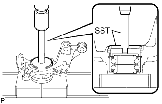
Using SST and a press, insert a new hub bearing, with its magnetic rotor side facing the inside of the vehicle, until it reaches the end of the steering knuckle.
- SST
- 09608-10010
- 09950-70010 ( 09951-07100 )
Note
-
Do not remove the inner race because the hub bearing is built into the oil seal.
-
Do not use bearings that have been removed.
-
Do not wipe off any grease that has been applied to new bearings.
-
Do not bring magnets close to the magnetic rotor surface of the bearing.
-
Keep the magnetic rotor surface of the bearing free of foreign matter.
-
-
INSTALL STEERING KNUCKLE (for 1ND-TV, 1NR-FE)
-
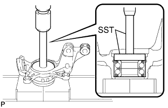
Using SST and a press, insert a new hub bearing, with its magnetic rotor side facing the inside of the vehicle, until it reaches the end of the steering knuckle.
- SST
- 09950-60020 ( 09951-00750 )
- 09950-70010 ( 09951-07100 )
Note
-
Do not remove the inner race because the hub bearing is built into the oil seal.
-
Do not use bearings that have been removed.
-
Do not wipe off any grease that has been applied to new bearings.
-
Do not bring magnets close to the magnetic rotor surface of the bearing.
-
Keep the magnetic rotor surface of the bearing free of foreign matter.
-
-
INSTALL FRONT DISC BRAKE DUST COVER
-
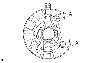
Provisionally install a new disc brake dust cover, as shown in the illustration.
Standard Clearance A Engine type Clearance A 1KR-FE 19.8 mm (0.780in.) 1ND-TV, 1NR-FE 25.5 mm (1.00in.) -
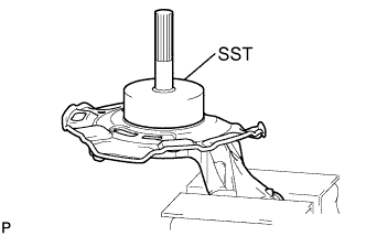
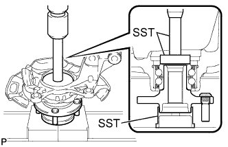
Using SST and a hammer, install the disc brake dust cover.
- SST
- 09223-56010
Note
-
Uniformly press in the disc brake dust cover while sliding SST slightly.
-
Surely press in the disc brake dust cover until it comes into contact with the pressing-in base.
-
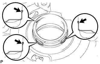
Using a chisel, fix the 3 points on the circumference.
Note
Securely fold each end into the engagement grooves.
-
-
INSTALL FRONT AXLE HUB SUB-ASSEMBLY (for 1KR-FE)
-
Using SST and a press, press the axle hub sub-assembly into the steering knuckle.
- SST
- 09608-32010
- 09950-60010 ( 09951-00520 )
- 09950-70010 ( 09951-07100 )
-
-
INSTALL FRONT AXLE HUB SUB-ASSEMBLY (for 1ND-TV, 1NR-FE)
-
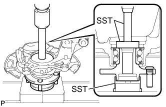
Using SST and a press, press the axle hub sub-assembly into the steering knuckle.
- SST
- 09608-32010
- 09950-60010 ( 09951-00560 )
- 09950-70010 ( 09951-07100 )
-
-
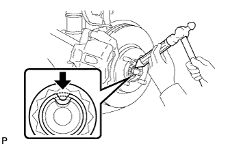
INSTALL FRONT AXLE HUB HOLE SNAP RING
-
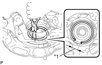
Text in Illustration *1 Speed Sensor Installation Hole Using snap ring pliers, install a new hole snap ring, as shown in the illustration.
Note
-
Do not overlap the end of the snap ring and the installation hole in the speed sensor on the knuckle side.
-
Do not damage the magnetic rotor surface of the bearing when installing the snap ring.
-
-
-
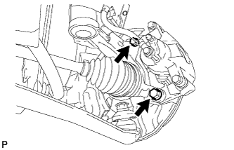
INSTALL FRONT AXLE ASSEMBLY
-
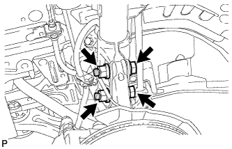
Install the front axle assembly onto the shock absorber.
-
Install the 2 bolts and 2 nuts.
- Torque:
- 164 N*m { 1672 kgf*cm, 121 ft.*lbf }
Note
Be careful not to damage the drive shaft boot or speed sensor rotor.
-
Push the front axle out of the vehicle to align the spline of the drive shaft with the front axle and insert the front axle.
-
-
INSTALL FRONT LOWER SUSPENSION ARM
-
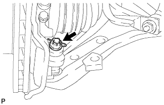
Install the lower arm onto the steering knuckle with a new castle nut.
- Torque:
- 98 N*m { 999 kgf*cm, 72 ft.*lbf }
-
Install a new clip.
-
-
INSPECT FRONT AXLE HUB BEARING LOOSENESS
-
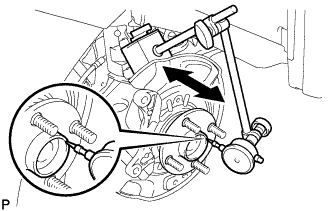
Using a dial indicator, check for looseness near the center of the axle hub.
Maximum looseness 0.05 mm (0.00197 in.) Tech Tips
-
Ensure that the dial indicator is set perpendicular to the measurement surface.
-
If looseness exceeds the maximum, replace the front axle hub bearing.
-
-
-
INSPECT FRONT AXLE HUB RUNOUT
-
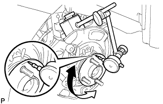
Using a dial indicator, check for runout on the surface of the axle hub outside the hub bolt.
Maximum runout 0.05 mm (0.00197 in.) Tech Tips
-
Ensure that the dial indicator is set perpendicular to the measurement surface.
-
If runout exceeds the maximum, replace the front axle hub sub-assembly.
-
-
-
INSTALL FRONT DISC
-
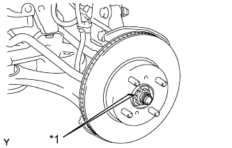
Text in Illustration *1 Matchmark Align the matchmarks of the disc and axle hub, and install the disc.
Note
When replacing the disc with a new one, select the installation position where the front disc has the minimal runout.
-
-
INSTALL FRONT DISC BRAKE CALIPER ASSEMBLY
-
Install the disc brake caliper onto the steering knuckle.
- Torque:
- 107 N*m { 1089 kgf*cm, 79 ft.*lbf }
-
-
CONNECT FRONT SPEED SENSOR
-
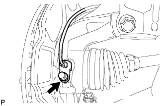
Install the front speed sensor onto the steering knuckle with the bolt.
- Torque:
- 8.5 N*m { 87 kgf*cm, 75 in.*lbf }
-
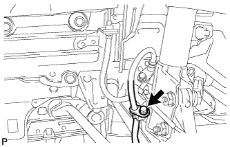
Install the flexible hose and front speed sensor with the bolt.
- Torque:
- 29 N*m { 300 kgf*cm, 22 ft.*lbf }
Tech Tips
Install the front speed sensor first and then the front flexible hose.
-
-
INSTALL FRONT AXLE HUB NUT
-
Clean the threaded parts on the drive shaft and axle hub nut using a non-residue solvent.
-
Using a 30 mm deep socket wrench, install a new axle hub nut.
- Torque:
- 216 N*m { 2203 kgf*cm, 159 ft.*lbf }
-
Using a chisel and hammer, caulk the axle hub nut.
-
-
INSTALL FRONT WHEEL
- Torque:
- 103 N*m { 1050 kgf*cm, 76 ft.*lbf }
-
INSPECT AND ADJUST FRONT WHEEL ALIGNMENT
Tech Tips
-
CHECK FOR SPEED SENSOR SIGNAL
Tech Tips