FRONT AXLE HUB ON-VEHICLE INSPECTION

Tech Tips
-
Use the same procedure for the RH side and LH side.
-
The procedure listed below is for the LH side.
-
REMOVE FRONT WHEEL
-
SEPARATE FRONT DISC BRAKE CALIPER ASSEMBLY
-
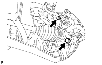
Remove the 2 bolts and separate the disc brake caliper from the steering knuckle.
-
-
REMOVE FRONT DISC
-
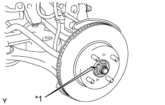
Text in Illustration *1 Matchmark Put matchmarks on the disc and the axle hub, and remove the front disc.
-
-
INSPECT FRONT AXLE HUB BEARING LOOSENESS
-
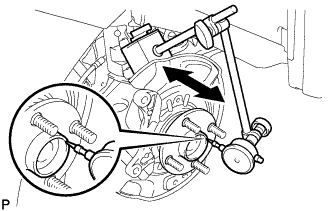
Using a dial indicator, check for looseness near the center of the axle hub.
Maximum looseness 0.05 mm (0.00197 in.) Tech Tips
-
Ensure that the dial indicator is set perpendicular to the measurement surface.
-
If looseness exceeds the maximum, replace the front axle hub bearing.
-
-
-
INSPECT FRONT AXLE HUB RUNOUT
-
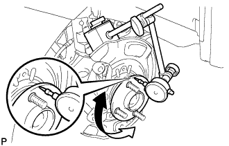
Using a dial indicator, check for runout on the surface of the axle hub outside the hub bolt.
Maximum runout 0.05 mm (0.00197 in.) Tech Tips
-
Ensure that the dial indicator is set perpendicular to the measurement surface.
-
If runout exceeds the maximum, replace the front axle hub sub-assembly.
-
-
-
INSTALL FRONT DISC
-
Text in Illustration *1 Matchmark Align the matchmarks of the disc and axle hub, and install the disc.
Note
When replacing the disc with a new one, select the installation position where the front disc has the minimal runout.
-
-
INSTALL FRONT DISC BRAKE CALIPER ASSEMBLY
-
Install the disc brake caliper onto the steering knuckle.
- Torque:
- 107 N*m { 1089 kgf*cm, 79 ft.*lbf }
-
-
INSTALL FRONT WHEEL
- Torque:
- 103 N*m { 1050 kgf*cm, 76 ft.*lbf }