FRONT DRIVE SHAFT ASSEMBLY (for 1ND-TV) INSTALLATION

-
INSTALL FRONT DRIVE SHAFT ASSEMBLY LH
-
Coat the spline of the inboard joint with gear oil.
-
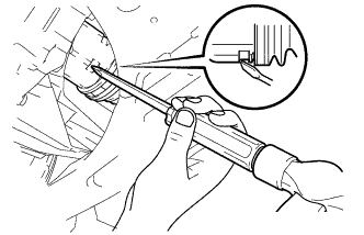
Align the inboard joint splines and install the drive shaft with a screwdriver and hammer.
Note
-
Face the gap of the front drive shaft hole snap ring downward.
-
Do not damage the oil seal.
-
Do not damage the inboard joint boot.
Tech Tips
Confirm whether the drive shaft is securely driven in by checking the reaction force and sound.
-
-
-
INSTALL FRONT DRIVE SHAFT ASSEMBLY RH
Tech Tips
Use the same procedure for the RH side as for the LH side.
-
INSTALL FRONT AXLE ASSEMBLY
-
Push the front axle out of the vehicle to align the splines of the drive shaft with the front axle and insert the front axle.
Note
-
Do not push the front axle further out of the vehicle than is necessary.
-
Do not damage the outboard joint boot.
-
Check for any foreign matter on the speed sensor rotor and insertion area.
-
Do not damage the speed sensor rotor.
-
-
-
INSTALL FRONT LOWER SUSPENSION ARM SUB-ASSEMBLY
-
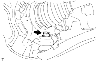
Install the lower arm onto the steering knuckle with a new castle nut.
- Torque:
- 98 N*m { 999 kgf*cm, 72 ft.*lbf }
Note
If the holes for the clip are not aligned, tighten the nut by a further turn of up to 60°.
-
Install a new clip.
-
-
INSTALL FRONT STABILIZER LINK ASSEMBLY
-
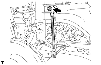
Install the stabilizer link with the nut.
- Torque:
- 74 N*m { 755 kgf*cm, 55 ft.*lbf }
Tech Tips
If the ball joint turns together with the nut, use a socket hexagon wrench 6 to hold the stud.
-
-
INSTALL FRONT SPEED SENSOR
-
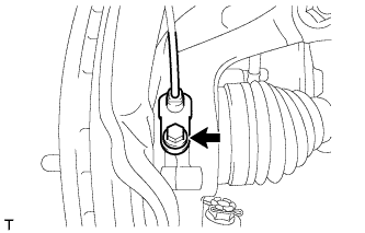
Install the speed sensor onto the steering knuckle with the bolt.
- Torque:
- 8.5 N*m { 87 kgf*cm, 75 in.*lbf }
Note
-
Check that the speed sensor tip and installation area are free of foreign matter.
-
Install the speed sensor without turning it from its original installation angle.
-
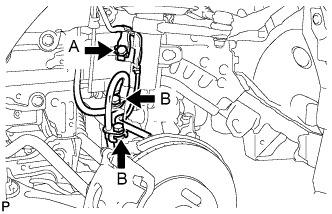
Install the flexible hose and speed sensor with the bolt.
- Torque:
- Bolt A
- 29 N*m { 296 kgf*cm, 21 ft.*lbf }
- Bolt B
- 29 N*m { 300 kgf*cm, 22 ft.*lbf }
Note
Install the flexible hose and speed sensor without twisting them.
-
-
INSTALL FRONT AXLE HUB NUT
-
Clean the threaded parts on the drive shaft and axle hub nut using a non-residue solvent.
Note
-
Be sure to perform this work for a new drive shaft.
-
Keep the threaded part free of oil and foreign objects.
-
-
Using a 30 mm deep socket wrench, install a new axle hub nut.
- Torque:
- 216 N*m { 2203 kgf*cm, 159 ft.*lbf }
-
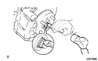
Using a chisel and hammer, stake the axle hub nut.
-
-
INSTALL FRONT WHEEL
- Torque:
- 103 N*m { 1050 kgf*cm, 76 ft.*lbf }
-
ADD MANUAL TRANSAXLE OIL
-
Install a new gasket and the manual transmission drain plug.
- Torque:
- 45 N*m { 459 kgf*cm, 33 ft.*lbf }
-
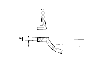
Text in Illustration *1 0 to 5 mm (0 to 0.20 in.) Add manual transaxle oil.
-
-
INSPECT MANUAL TRANSAXLE OIL
-
Text in Illustration *1 0 to 5 mm (0 to 0.20 in.) Check that the oil surface is within 5 mm (0.20 in.) of the bottom of the manual transmission filler plug opening.
Note
Excessively large or small amounts of oil may cause problems.
-
Check for oil leakage when the oil level is low.
-
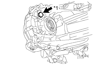
Text in Illustration *1 Filler plug Install the manual transmission filler plug and a new gasket.
- Torque:
- 39 N*m { 400 kgf*cm, 29 ft.*lbf }
-
-
INSPECT FOR MANUAL TRANSAXLE LEAK
-
INSPECT AND ADJUST FRONT WHEEL ALIGNMENT
-
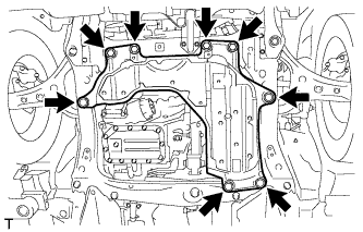
INSTALL ENGINE UNDER COVER
-
Install the engine under cover assembly with the 4 bolts and the 4 clips.
- Torque:
- 5.0 N*m { 51 kgf*cm, 44 in.*lbf }
-
-
CHECK FOR SPEED SENSOR SIGNAL