FRONT DRIVE SHAFT ASSEMBLY (for 1ND-TV) REMOVAL

-
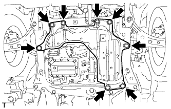
REMOVE ENGINE UNDER COVER
-
Remove the 4 bolts, 4 clips and the engine under cover.
-
-
DRAIN MANUAL TRANSAXLE OIL
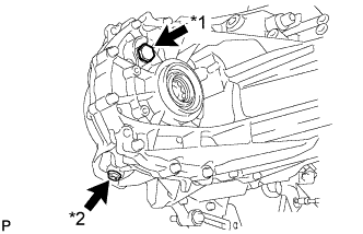
Text in Illustration *1 Filler plug *2 Drain plug
-
Stop the vehicle in a level place.
-
Remove the manual transmission filler plug and the gasket.
-
Remove the manual transmission drain plug and gasket, and then drain the manual transaxle oil.
-
-
REMOVE FRONT WHEEL
-
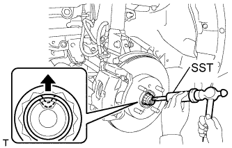
REMOVE FRONT AXLE HUB NUT
-
Using SST and a hammer, release the staked part of the axle hub nut.
- SST
- 09930-00010
Note
-
Insert SST into the groove with the flat surface facing up.
-
Do not damage the tip of SST using a grinder.
-
Completely unstake the staked part before removing the axle hub nut.
-
Do not damage the threads of the drive shaft.
-
Using a 30 mm socket wrench, remove the axle hub nut.
-
-
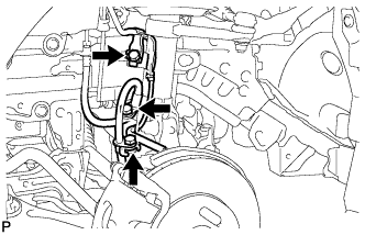
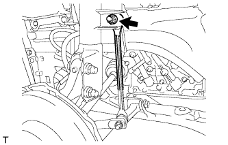
SEPARATE FRONT SPEED SENSOR
-
Remove the 3 bolts and separate the speed sensor and flexible hose.
-
Remove the bolt and separate the speed sensor from the steering knuckle.
Note
-
Keep the speed sensor tip and installation area free of foreign matter.
-
Remove the speed sensor without turning it from its original installation angle.
-
-
-
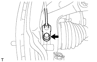
SEPARATE FRONT STABILIZER LINK ASSEMBLY
-
Remove the nut and separate the stabilizer link from the shock absorber.
-
-
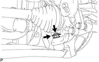
SEPARATE FRONT LOWER SUSPENSION ARM SUB-ASSEMBLY
-
Remove the clip and castle nut.
-
Install SST (spacer B) to the threaded section of the lower ball joint.
- SST
- 09960-20010 ( 09961-02060 )
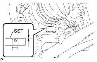
Note
Make sure the upper ends of the threaded section of the lower ball joint and SST (spacer B) are aligned.
-
Using SST, separate the front lower suspension arm from the front axle assembly.
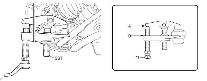
Text in Illustration *1 Place the wrench here - SST
- 09960-20010 ( 09961-02010 )
Note
-
Make sure to tie the string of SST to the vehicle to prevent SST from dropping.
-
Install SST so that A and B are parallel.
-
Be sure to place the wrench on the part indicated in the illustration.
-
Do not damage the lower ball joint dust cover.
-
Do not damage the drive shaft outboard joint boots.
-
Do not damage the front disc brake dust cover.
-
-
SEPARATE FRONT AXLE ASSEMBLY
-
Using a plastic hammer, tap the end of the drive shaft and disengage the fitting between the drive shaft and front axle.
Tech Tips
If it is difficult to disengage the fitting, tap the end of the drive shaft with a brass bar and hammer.
-
Push the front axle out of the vehicle to remove the drive shaft from the front axle.
Note
-
Do not push the front axle further out of the vehicle than is necessary.
-
Do not damage the outboard joint boot.
-
Do not damage the speed sensor rotor.
-
Suspend the drive shaft with a piece of string or the equivalent.
-
-
-
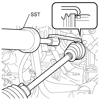
REMOVE FRONT DRIVE SHAFT ASSEMBLY LH
-
Using SST, remove the drive shaft.
- SST
- 09520-01010
- 09520-24010 ( 09520-32040 )
Note
-
Do not damage the oil seal.
-
Do not damage the inboard joint boot.
-
Do not drop the drive shaft.
-
-
REMOVE FRONT DRIVE SHAFT ASSEMBLY RH
Tech Tips
Use the same procedure for the RH side as for the LH side.
-
FIX FRONT AXLE ASSEMBLY
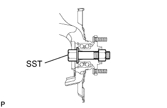
- SST
- 09608-16042 ( 09608-02021, 09608-02041 )
Tech Tips
The hub bearing could be damaged if it is subjected to the vehicle's full weight, such as when moving the vehicle with the drive shaft removed. If it is absolutely necessary to place the vehicle's full weight on the hub bearing, first support it with SST.