FRONT DRIVE SHAFT ASSEMBLY (for 1KR-FE) INSTALLATION

-
INSTALL FRONT DRIVE SHAFT ASSEMBLY LH
-
Coat the spline of the inboard joint with gear oil.
-
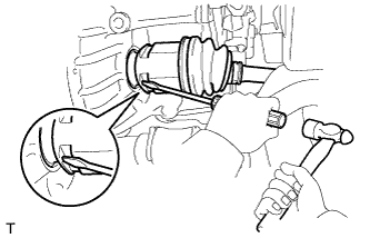
Align the inboard joint splines and install the drive shaft with a screwdriver and hammer.
Note
-
Face the cut area of the front drive inboard joint hole snap ring downward.
-
Do not damage the oil seal.
-
Do not damage the inboard joint boot.
Tech Tips
Confirm whether the drive shaft is securely driven in by checking the reaction force and sound.
-
-
-
INSTALL FRONT DRIVE SHAFT ASSEMBLY RH
-
Coat the spline of the inboard joint shaft assembly with gear oil.
-
Install the drive shaft assembly.
-
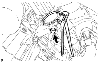
Using water pump pliers, install a new bearing bracket hole snap ring.
Note
Do not damage the boot and oil seal.
-
Install a new bolt.
- Torque:
- 32 N*m { 330 kgf*cm, 24 ft.*lbf }
Note
Before installing a new bolt, check that there is rubber on the tip of a new bolt. If there is no rubber on the bolt, use a new one.
-
-
INSTALL FRONT AXLE ASSEMBLY
-
Push the front axle out of the vehicle to align the splines of the drive shaft with the front axle and insert the front axle.
Note
-
Do not push the front axle further out of the vehicle than is necessary.
-
Do not damage the outboard joint boot.
-
Check for any foreign matter on the speed sensor rotor and insertion area.
-
Do not damage the speed sensor rotor.
-
-
-
INSTALL FRONT LOWER SUSPENSION ARM SUB-ASSEMBLY
-
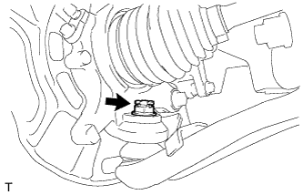
Install the lower arm onto the steering knuckle with a new castle nut.
- Torque:
- 98 N*m { 999 kgf*cm, 72 ft.*lbf }
Note
If the holes for the clip are not aligned, tighten the nut by a further turn of up to 60°.
-
Install a new clip.
-
-
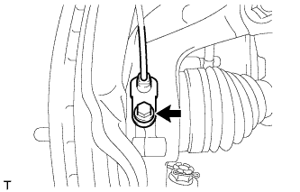
INSTALL FRONT STABILIZER LINK ASSEMBLY
-
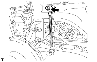
Install the stabilizer link with the nut.
- Torque:
- 74 N*m { 755 kgf*cm, 55 ft.*lbf }
Tech Tips
If the ball joint turns together with the nut, use a socket hexagon wrench 6 to hold the stud.
-
-
INSTALL FRONT SPEED SENSOR
-
Install the speed sensor onto the steering knuckle with the bolt.
- Torque:
- 8.5 N*m { 87 kgf*cm, 75 in.*lbf }
Note
-
Check that the speed sensor tip and installation area are free of foreign matter.
-
Install the speed sensor without turning it from its original installation angle.
-
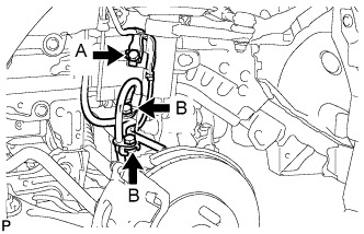
Install the flexible hose and speed sensor with the bolt.
- Torque:
- Bolt A
- 29 N*m { 296 kgf*cm, 21 ft.*lbf }
- Bolt B
- 29 N*m { 300 kgf*cm, 22 ft.*lbf }
Note
Install the flexible hose and speed sensor without twisting them.
-
-
INSTALL FRONT AXLE HUB NUT
-
Clean the threaded parts on the drive shaft and axle hub nut using a non-residue solvent.
Note
-
Be sure to perform this work for a new drive shaft.
-
Keep the threaded part free of oil and foreign objects.
-
-
Using a 30 mm deep socket wrench, install a new axle hub nut.
- Torque:
- 216 N*m { 2203 kgf*cm, 159 ft.*lbf }
-
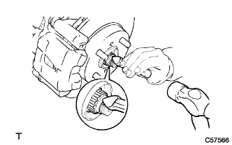
Using a chisel and hammer, stake the axle hub nut.
-
-
INSTALL FRONT WHEEL
- Torque:
- 103 N*m { 1050 kgf*cm, 76 ft.*lbf }
-
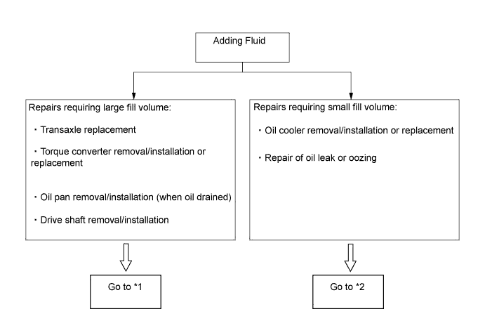
ADD CVT FLUID (for CVT)
Tech Tips
Refer to the following diagram when adding fluid.
-
When adding fluid (large fill volume) *1
-
Be sure that the vehicle remains level and lift the vehicle.
-
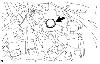
Use a socket hexagon wrench (6 mm) to remove the drain plug and gasket.
-
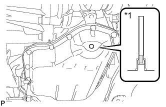
Text in Illustration *1 No. 1 Transmission Oil Filler Tube Use a socket hexagon wrench (6 mm) to check that the No. 1 transmission oil filler tube is tightened to the specified torque.
- Torque:
- 0.8 N*m { 8.2 kgf*cm, 7 in.*lbf }
Note
If the No. 1 transmission oil filler tube is not tightened to the specified torque, then the fluid level cannot be adjusted correctly.
-
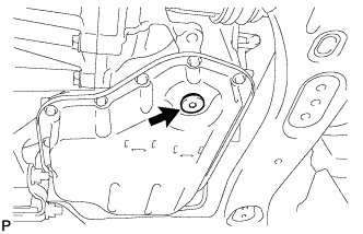
Remove the refill plug and gasket.
-
Add fluid into the refill hole until it flows out from the overflow hole.
Note
This transmission requires Toyota Genuine CVT Fluid TC.
-
Wait until the steady flow slows to a trickle, install a gasket, and temporarily tighten the drain plug with a socket hexagon wrench (6 mm).
Tech Tips
Because the drain plug will be removed again, the gasket can be reused at this time.
-
Fill the specified volume of transmission fluid into the refill hole.
Note
The fill amount varies depending on the procedures being completed.
Reference Capacity Related Procedure Fill Volume Transaxle replacement (with a new torque converter) 1.4 liters (1.48 US qts, 1.23 Imp. qts) Transaxle replacement (when reusing the torque converter) 0.4 liters (0.42 US qts, 0.35 Imp. qts) Torque converter replacement 1.6 liters (1.69 US qts, 1.41 Imp. qts) Torque converter removal/installation 0.4 liters (0.42 US qts, 0.35 Imp. qts) Oil pan removal/installation (when oil drained) 0.4 liters (0.42 US qts, 0.35 Imp. qts) Drive shaft removal/installation 0.4 liters (0.42 US qts, 0.35 Imp. qts) -
Install the gasket and temporarily tighten the refill plug.
Tech Tips
Because the refill plug will be removed again, the gasket can be reused at this time.
-
Lower the vehicle.
-
-
When refilling (small fill volume) *2
-
Be sure that the vehicle remains level and lift the vehicle.
-
Remove the refill plug and gasket.
-
Fill the specified volume of transmission fluid into the refill hole.
Reference Capacity Related Procedure Fill Volume Oil cooler removal/installation or replacement 0.4 liters (0.42 US qts, 0.35 Imp. qts) Repair of oil seeping or oozing 0.4 liters (0.42 US qts, 0.35 Imp. qts) -
Install the gasket and temporarily tighten the refill plug.
Tech Tips
Because the refill plug will be removed again, the gasket can be reused at this time.
-
Lower the vehicle.
-
-
-
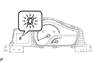
FLUID TEMPERATURE CHECK (for CVT)
Note
The fluid temperature can be confirmed by checking the indicator light in the meter or by using the intelligent tester. When using the intelligent tester, it is necessary to change to temperature detection mode in order to idle the vehicle appropriately.
-
When using the intelligent tester
-
Turn the ignition switch off.
-
Connect the intelligent tester to the DLC3.
-
Turn the ignition switch to ON.
-
Turn the tester on.
-
Enter the following menus: Powertrain / Engine and ECT / Data Test / A/T Oil Temperature 1.
-
Enter the following menus: Powertrain / Engine and ECT / Active Test / Connect the TC and TE1.
-
-
When not using the intelligent tester
-
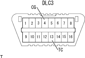
Using SST, connect terminals 13 (TC) and 4 (CG) of the DLC3.
-
-
Start the engine.
Note
Check that electrical systems such as the air conditioning system, audio system and lighting system are off.
Tech Tips
Indicator lights of the meter blink to output DTCs when terminals TC and CG are connected.
-
Slowly move the shift lever from P to B and back to P again.
Tech Tips
Hold the shift lever in each position for about 3 seconds.
-
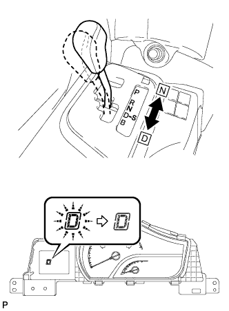
Move the shift lever to D, and then continuously move the shift lever back and forth between N and D at a rate of 1 shift/1.5 seconds or faster for 6 seconds or more. This will activate the fluid temperature detection mode.
Standard condition The indicator light (D) remains illuminated for 2 seconds and then turns off. -
Return the shift lever to P.
-
The indicator light (D) remains off, illuminates, or blinks depending on the fluid temperature.
Indicator Light (D) Remains OFF Illuminates Blinks Below 35 °C (95°F) 35 °C (95 °F) to
45 °C (113 °F)
45 °C (113 °F) or higher Below proper temperature Proper temperature range Above proper temperature -
If the indicator remains off or illuminates, disconnect the TC terminal and perform the "Fluid Level Check".
Note
-
If the TC terminal is not OFF (open), accurate fluid level adjustment is not possible, so be sure to disconnect this terminal.
-
If the TC terminal is not OFF (open), in some cases, the fluid temperature reading will immediately exceed the proper temperature for adjustment.
-
If the light is blinking, stop the engine, wait for the fluid temperature to decrease, and repeat the procedure from "Fluid Temperature Check".
-
-
-
FLUID LEVEL CHECK (for CVT)
-
Idle the engine to warm it up, and ensure that the fluid temperature is correct.
-
Lift the vehicle immediately after the indicator light (D) illuminates.
Note
Adjust the fluid level while the indicator light (D) is illuminated.
-
Use a socket hexagon wrench (6 mm) to remove the drain plug and gasket, and then check the fluid condition.
Tech Tips
-
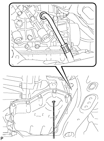
Check that the fluid flows out from the overflow tube.
-
If the volume of fluid that flows out is small, it is possible that fluid was remaining in the tube (about 5 cc (0.30512 cu in.)), so assume that there was no overflow.
-
-
If the fluid overflows
-
Wait until the steady flow slows to a trickle, and then use a socket hexagon wrench (6 mm) to install a new gasket and tighten the drain plug.
- Torque:
- 40 N*m { 408 kgf*cm, 30 ft.*lbf }
-
Replace the refill plug with a new gasket and tighten the refill plug.
- Torque:
- 49 N*m { 500 kgf*cm, 36 ft.*lbf }
-
-
If the fluid does not overflow
-
Remove the refill plug and gasket.
-
Add fluid into the refill hole until it flows out from the overflow hole.
Note
This transmission requires Toyota Genuine CVT Fluid TC.
-
Wait until the steady flow slows to a trickle, and then install a new gasket and tighten the drain plug.
- Torque:
- 40 N*m { 408 kgf*cm, 30 ft.*lbf }
-
Install a new gasket and fully tighten the refill plug.
- Torque:
- 49 N*m { 500 kgf*cm, 36 ft.*lbf }
-
-
Lower the vehicle.
-
Turn the ignition switch off and disconnect the intelligent tester.
-
-
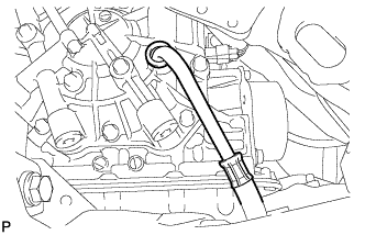
INSPECT FOR CONTINUOUSLY VARIABLE TRANSAXLE FLUID LEAK (for CVT)
-
Clean the area and check for fluid leaks.
-
-
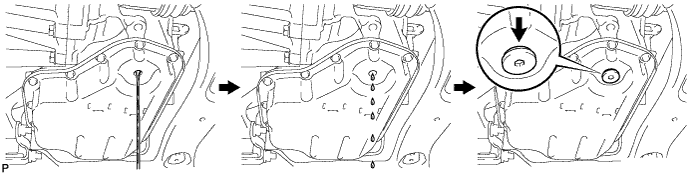
ADD MANUAL TRANSAXLE OIL (for Manual Transaxle)
-
Install a new gasket and the manual transmission drain plug.
- Torque:
- 45 N*m { 459 kgf*cm, 33 ft.*lbf }
-
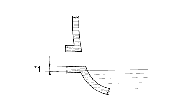
Text in Illustration *1 0 to 5 mm (0 to 0.20 in.) Add manual transaxle oil.
-
-
INSPECT MANUAL TRANSAXLE OIL (for Manual Transaxle)
-
Text in Illustration *1 0 to 5 mm (0 to 0.20 in.) Check that the oil surface is within 5 mm (0.20 in.) of the bottom of the manual transmission filler plug opening.
Note
Excessively large or small amounts of oil may cause problems.
-
Check for oil leakage when the oil level is low.
-
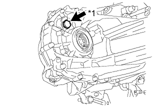
Text in Illustration *1 Filler plug Install the manual transmission filler plug and a new gasket.
- Torque:
- 39 N*m { 400 kgf*cm, 29 ft.*lbf }
-
-
INSPECT FOR MANUAL TRANSAXLE OIL LEAK (for Manual Transaxle)
-
INSPECT AND ADJUST FRONT WHEEL ALIGNMENT
-
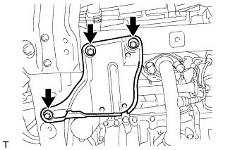
INSTALL ENGINE UNDER COVER NO. 2
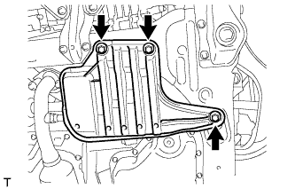
-
Install the engine under cover No. 2 with the 3 bolts.
- Torque:
- 5.0 N*m { 51 kgf*cm, 44 in.*lbf }
-
-
INSTALL ENGINE UNDER COVER NO. 1
-
Install the engine under cover No. 1 with the 3 bolts.
- Torque:
- 5.0 N*m { 51 kgf*cm, 44 in.*lbf }
-
-
CHECK FOR SPEED SENSOR SIGNAL