FRONT SUSPENSION MEMBER INSTALLATION

-
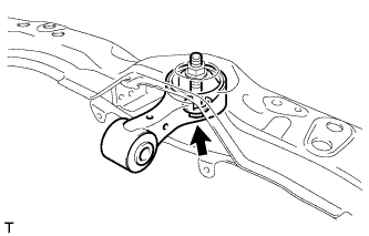
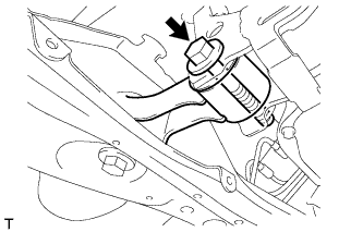
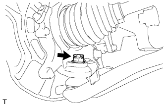
INSTALL ENGINE MOVING CONTROL ROD
-
Install the engine moving control rod with the bolt.
- Torque:
- 100 N*m { 1020 kgf*cm, 74 ft.*lbf }
-
-
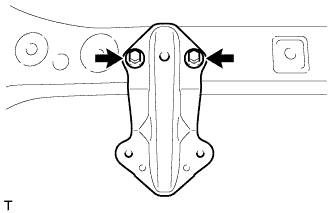
INSTALL ENGINE MOVING CONTROL ROD COVER (for Cold Area)
-
Install the engine moving control rod cover with the 2 clips.
-
-
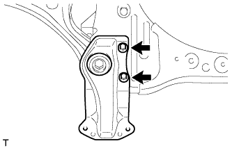
INSTALL FRONT SUSPENSION MEMBER DYNAMIC DAMPER (for 1NR-FE)
-
Install the front suspension member dynamic damper with the bolt.
- Torque:
- 30 N*m { 306 kgf*cm, 22 ft.*lbf }
-
-
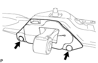
INSTALL FRONT BUMPER GUARD LH
-
Install the side bumper guard sub-assembly LH with the 2 bolts.
- Torque:
- 5.0 N*m { 51 kgf*cm, 44 in.*lbf }
-
-
INSTALL FRONT BUMPER GUARD RH
Tech Tips
Use the same procedure for the RH side as for the LH side.
-
INSTALL FRONT BUMPER GUARD
-
Install the front bumper guard sub-assembly with the 2 bolts.
- Torque:
- 5.0 N*m { 51 kgf*cm, 44 in.*lbf }
-
-
TEMPORARILY TIGHTEN FRONT LOWER SUSPENSION ARM SUB-ASSEMBLY LH
-
Provisionally tighten the lower arm with 2 new bolts and the nut.
-
-
TEMPORARILY TIGHTEN FRONT LOWER SUSPENSION ARM SUB-ASSEMBLY RH
Tech Tips
Use the same procedure for the RH side as for the LH side.
-
INSTALL FRONT STABILIZER BAR
-
INSTALL FRONT STABILIZER BRACKET LH
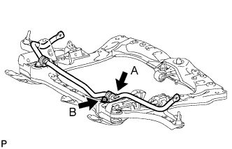
-
Provisionally tighten bolt A.
-
Tighten the bolts to the specified torque, in the order of B then A.
- Torque:
- 55 N*m { 561 kgf*cm, 41 ft.*lbf }
-
-
INSTALL FRONT STABILIZER BRACKET RH
Tech Tips
Use the same procedure for the RH side as for the LH side.
-
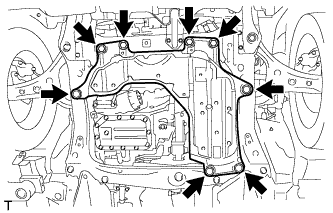
INSTALL FRONT FRAME ASSEMBLY
-
Support the front frame assembly with 4 wooden blocks and the jack.
-
Provisionally install the front frame assembly onto the body with the 6 bolts.
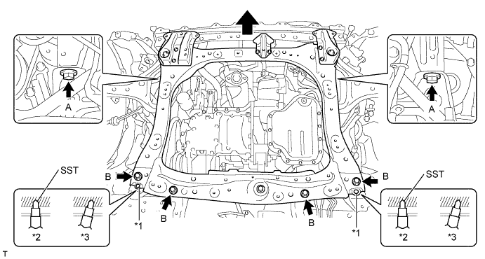
Text in Illustration *1 Datum Hole *2 OK *3 NG Bolt Underhead Length (mm) A 38 B 69 -
By inserting SST into the datum holes in the front frame assembly RH and LH alternately, tighten bolts A and B on both sides to the specified torque, in several steps.
- SST
- 09670-00011
- Torque:
- 108 N*m { 1101 kgf*cm, 80 ft.*lbf, for bolt A }
- 120 N*m { 1224 kgf*cm, 89 ft.*lbf, for bolt B }
Note
-
Insert SST into the datum hole in a vertical orientation.
-
If SST can not be inserted into the datum hole vertically, loosen all the bolts and then insert SST again.
-
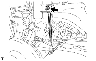
Install the engine moving control rod to engine mounting control bracket with the bolt.
- Torque:
- 120 N*m { 1224 kgf*cm, 89 ft.*lbf }
-
Remove the strong rope from engine mounting control bracket and body.
-
-
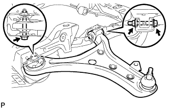
INSTALL FRONT LOWER SUSPENSION ARM SUB-ASSEMBLY LH
-
Install the lower arm onto the steering knuckle with a new castle nut.
- Torque:
- 98 N*m { 999 kgf*cm, 72 ft.*lbf }
Note
If the holes for the clip are not aligned, tighten the nut by a further turn of up to 60°.
-
Install a new clip.
-
-
INSTALL FRONT LOWER SUSPENSION ARM SUB-ASSEMBLY RH
Tech Tips
Use the same procedure for the RH side as for the LH side.
-
INSTALL FRONT STABILIZER LINK ASSEMBLY LH
-
Install the stabilizer link with the nut.
- Torque:
- 74 N*m { 755 kgf*cm, 55 ft.*lbf }
Tech Tips
If the ball joint turns together with the nut, use a socket hexagon wrench 6 to hold the stud.
-
-
INSTALL FRONT STABILIZER LINK ASSEMBLY RH
Tech Tips
Use the same procedure for the RH side as for the LH side.
-
INSTALL FRONT WHEEL
- Torque:
- 103 N*m { 1050 kgf*cm, 76 ft.*lbf }
-
POSITION WHEELS FACING STRAIGHT AHEAD
-
STABILIZE SUSPENSION
-
Lower the vehicle from the jack.
-
Bounce the vehicle up and down several times to stabilize the suspension.
-
-
FULLY TIGHTEN FRONT LOWER SUSPENSION ARM SUB-ASSEMBLY LH
-
Fully tighten the 2 bolts and the nut.
- Torque:
- 145 N*m { 1479 kgf*cm, 107 ft.*lbf }
-
-
FULLY TIGHTEN FRONT LOWER SUSPENSION ARM SUB-ASSEMBLY RH
-
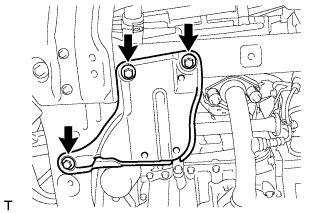
INSTALL ENGINE UNDER COVER NO. 2 (for 1KR-FE, 1NR-FE)
-
Install the engine under cover No. 2 with the 3 bolts.
- Torque:
- 5.0 N*m { 51 kgf*cm, 44 in.*lbf }
-
-
INSTALL ENGINE UNDER COVER NO. 1 (for 1KR-FE)
-
Install the engine under cover No. 1 with the 3 bolts.
- Torque:
- 5.0 N*m { 51 kgf*cm, 44 in.*lbf }
-
-
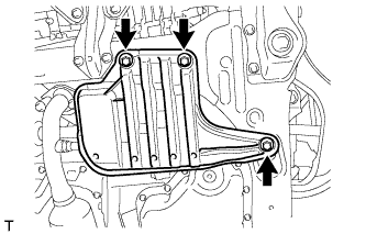
INSTALL ENGINE UNDER COVER (for 1ND-TV)
-
Install the engine under cover assembly with the 4 bolts and the 4 clips.
- Torque:
- 5.0 N*m { 51 kgf*cm, 44 in.*lbf }
-
-
INSTALL ENGINE UNDER COVER NO. 3
-
INSTALL FRONT FLOOR COVER LH
-
INSTALL FRONT FLOOR COVER RH
-
INSTALL FRONT BUMPER ASSEMBLY
-
Install the front bumper assembly Click here.
-
-
INSPECT AND ADJUST FRONT WHEEL ALIGNMENT
-
CHECK FOR SPEED SENSOR SIGNAL