PARK / NEUTRAL POSITION SWITCH INSTALLATION
-
INSTALL PARK/NEUTRAL POSITION SWITCH ASSEMBLY
-
Temporarily install the park/neutral position switch with the 2 bolts.
-
Install the nut and a new nut stopper.
- Torque:
- 6.9 N*m { 70 kgf*cm, 61 in.*lbf }
-
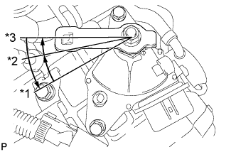
Text in Illustration *1 P Position *2 R Position *3 N Position Temporarily install the transmission control shaft lever, rotate it counterclockwise until it stops, rotate it clockwise for 2 notches to the N position, and then remove the transmission control shaft lever.
-
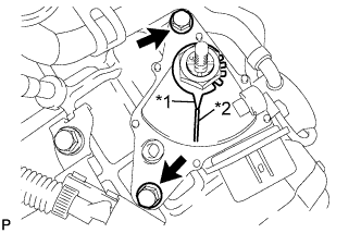
Text in Illustration *1 Nut Stopper Protrusion *2 Neutral Reference Line Align the neutral reference line with the protrusion on the nut stopper and fully tighten the 2 bolts.
- Torque:
- 5.4 N*m { 55 kgf*cm, 48 in.*lbf }
-
Bend the tabs of the nut stopper with a screwdriver.
-
Install the transmission control shaft lever and spring washer, and tighten the nut.
- Torque:
- 12 N*m { 122 kgf*cm, 9 ft.*lbf }
-
Connect the park/neutral position switch connector.
-
-
INSTALL TRANSMISSION CONTROL CABLE ASSEMBLY
-
Using the nut, connect the transmission control cable to the transmission control shaft lever.
- Torque:
- 12 N*m { 122 kgf*cm, 9 ft.*lbf }
Note
Confirm that the shift lever is in the N position.
-
-
INSPECT SHIFT LEVER POSITION
-
Turn the ignition switch to ON and step on the brake pedal.
-
Confirm that the shift lever moves smoothly through all of the shift positions and the position indicator shows the correct shift lever position.
-
Start the engine and confirm that the vehicle moves forward when the shift lever is moved from N to D.
-
-
ADJUST SHIFT LEVER POSITION
-
Remove the console panel upper Click here.
-
Move the shift lever to N.
-
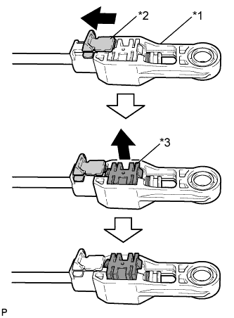
Text in Illustration *1 Adjuster Case *2 Cover *3 Lock Piece Slide the adjuster case cover in the direction shown by the arrow.
-
Using a precision screwdriver, pull up the lock piece.
-
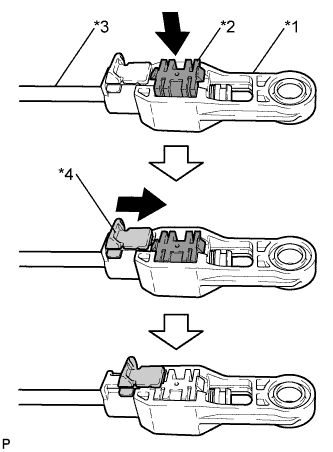
Text in Illustration *1 Adjuster Case *2 Lock Piece *3 Cable Rod *4 Cover Press the lock piece into the adjuster case.
Tech Tips
Lightly pull the cable rod towards the back of the vehicle to eliminate slack, and then lock the adjuster.
-
Slide the adjuster case cover in the direction shown by the arrow.
Note
If the cover is not pushed over the protrusion on the lock, the cable will not lock and shift operation will not be accurate.
-
Install the console panel upper Click here.
-