CONTINUOUSLY VARIABLE TRANSAXLE ASSEMBLY INSTALLATION

-
INSTALL TRANSMISSION CASE PLUG ASSEMBLY
Tech Tips
After replacing the CVT, perform the following procedure.
-
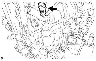
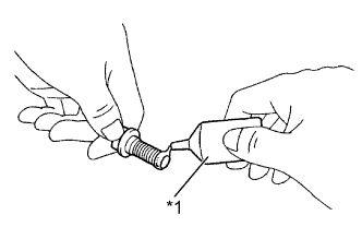
Apply Toyota Genuine CVT Fluid TC to the O-ring on a new transmission case plug.
-
Install the transmission case plug onto the CVT.
-
-
INSTALL WIRE HARNESS CLAMP BRACKET
-
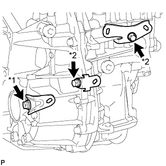
- Torque:
- *1
- 29 N*m { 296 kgf*cm, 21 ft.*lbf }
- *2
- 13 N*m { 133 kgf*cm, 10 ft.*lbf }
Use the 3 bolts to install the 3 wire harness clamp brackets to the CVT.
- Torque:
- *1
- 29 N*m { 296 kgf*cm, 21 ft.*lbf }
- *2
- 13 N*m { 133 kgf*cm, 10 ft.*lbf }
-
Use the 2 bolts to install the 2 wire harness clamp brackets to the CVT.
- Torque:
- 13 N*m { 133 kgf*cm, 10 ft.*lbf }
-
-
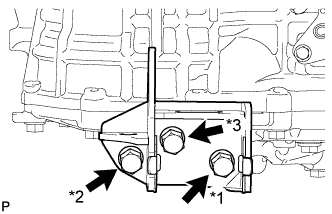
INSTALL NO. 1 TRANSMISSION CONTROL CABLE BRACKET
-
Install the No. 1 transmission control cable bracket onto the CVT with the 2 bolts.
- Torque:
- 12 N*m { 122 kgf*cm, 9 ft.*lbf }
-
-
INSTALL ENGINE MOUNTING BRACKET LH
-
Clean and degrease the bolts and the installation holes in the engine mounting bracket LH.
-
Apply adhesive to 2 or 3 threads on the ends of the 3 bolts.
Text in Illustration *1 Adhesive Adhesive Toyota Genuine Adhesive 1324, Three Bond 1324 or equivalent -
Install the engine mounting bracket LH onto the CVT with the 3 bolts.
- Torque:
- 64 N*m { 653 kgf*cm, 47 ft.*lbf }
Tech Tips
*1 (Temporarily tighten) →
*2 (Fully tighten) →
*3 (Fully tighten) →
*1 (Fully tighten)
-
-
INSTALL ENGINE MOUNTING STAY LH
-
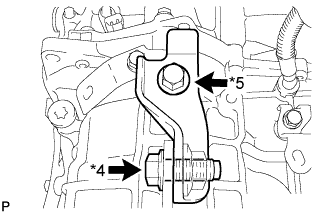
Install the engine mounting stay LH onto the CVT and engine mounting bracket LH with the 2 bolts.
- Torque:
- 64 N*m { 653 kgf*cm, 47 ft.*lbf }
Tech Tips
*4 (Temporarily tighten) →
*5 (Fully tighten) →
*4 (Fully tighten)
-
-
INSTALL CVT OIL PUMP TYPE T OIL SEAL
-
Ensure that there is no dirt or foreign matter on your hands, and then apply genuine TOYOTA MP grease No.2 to the entire periphery of the lip of a new CVT oil pump type T oil seal.
-
Temporarily attach the CVT oil pump type T oil seal by pressing it onto the installation surface of the oil pump housing manually.
-
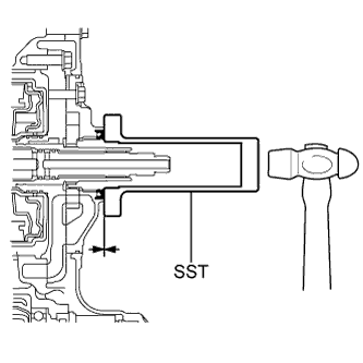
Clean the oil seal contact section of the SST and the area around it.
-
Using the SST, drive the CVT oil pump type T oil seal in evenly, as far as the side surface of the oil pump housing.
- SST
- 09309-36010
Note
-
Drive the oil seal in gradually, while visually checking the parallelism.
-
After the installation, confirm that the oil seal has been driven in as far as the side surface of the oil pump housing.
-
Wipe off any grease that has oozed out with your hand.
Tech Tips
The oil seal should be driven in between 0 and 0.5mm (as measured from the side surface of the oil pump housing).
-
-
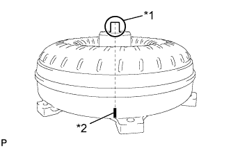
INSTALL TORQUE CONVERTER ASSEMBLY
-
Clean and degrease the 6 holes for the torque converter set bolts.
-
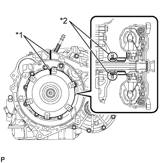
Make a matchmark to indicate the position of the torque converter protrusion (*1).
Text in Illustration *1 Protrusion *2 Matchmark -
Text in Illustration *1 Wide Groove *2 Narrow Groove *3 Matchmark Make a matchmark on the housing to indicate the position of the groove in the front oil pump drive gear.
Note
Make the housing matchmark at the wide groove. The matchmark position must be correct to prevent damage.
-
Text in Illustration *1 Matchmark *2 Oil Seal Align the matchmarks on the housing and torque converter and engage the input shaft splines with the turbine runner.
Note
-
Maintain the torque converter in a horizontal position when installing the input shaft.
-
Be sure to not damage the oil seal.
-
-
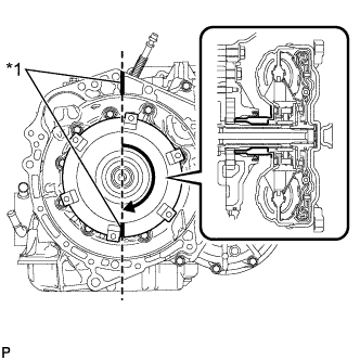
Text in Illustration *1 Matchmark Rotate the torque converter to engage the stator shaft splines with the stator splines.
Note
Maintain the torque converter in a horizontal position when installing the stator shaft.
Tech Tips
Rotate the torque converter about 180 degrees.
-
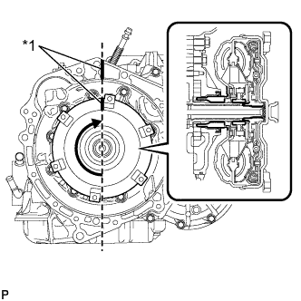
Text in Illustration *1 Matchmark Rotate the torque converter clockwise until the matchmark aligns with the matchmark on the case, and then engage the grooves in the oil pump drive gear with the claws in the torque converter.
Note
-
Maintain the torque converter in a horizontal position when installing the input shaft and stator shaft.
-
Do not push the torque converter while aligning the matchmarks.
-
-
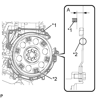
Text in Illustration *1 CVT Installation Surface *2 Torque Converter Installation Surface Using a vernier caliper, measure the distance from the CVT fitting surface on the engine to the torque converter fitting surface on the drive plate (dimension A).
-
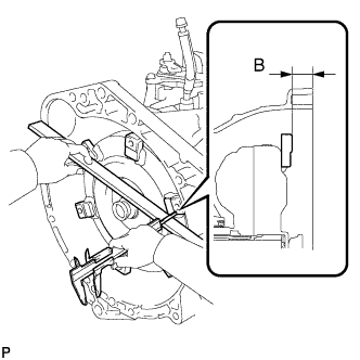
Using a vernier caliper and a straightedge, measure the distance from the set block to the housing end (dimension B) and check that dimension B is greater than dimension A.
Standard distance B=A+1 mm (0.0394 in.) or more Note
Ensure that the torque converter is inserted all the way into the CVT. If the converter is not inserted sufficiently when the CVT is installed onto the engine, the CVT and torque converter could be damaged.
-
-
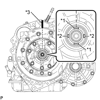
INSTALL CONTINUOUSLY VARIABLE TRANSAXLE
-
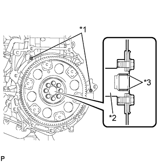
Text in Illustration *1 Knock Pin *2 Crankshaft Confirm that 2 knock pins are on the transaxle contact surface of the engine cylinder block before transaxle installation.
-
Apply clutch spline grease to the round of the crankshaft contact surface (*3) with the torque converter centerpiece.
Clutch spline grease Toyota Genuine Clutch Spline Grease or equivalent Maximum spread Approximately 1 g (0.353 oz) -
- Torque:
- *1
- 64 N*m { 653 kgf*cm, 47 ft.*lbf }
- *2
- 37 N*m { 377 kgf*cm, 27 ft.*lbf }
- *3
- 39 N*m { 398 kgf*cm, 29 ft.*lbf }
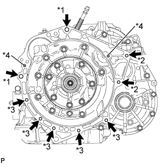
Maintain the engine and CVT in a horizontal position, align the knock pins and holes (*4), and tighten the 9 bolts shown the illustration.
- Torque:
- *1
- 64 N*m { 653 kgf*cm, 47 ft.*lbf }
- *2
- 37 N*m { 377 kgf*cm, 27 ft.*lbf }
- *3
- 39 N*m { 398 kgf*cm, 29 ft.*lbf }
Note
-
Confirm that there are 2 knock pins on the fitting surface of the engine block before installing the CVT.
-
Do not twist or apply excessive force to the CVT.
-
Check that the torque converter rotates smoothly after installation of the CVT.
Tech Tips
-
*1: 45 mm (1.77 in.)
-
*2: 45 mm (1.77 in.)
-
*3: 35 mm (1.38 in.)
Bolt length
-
-
INSTALL DRIVE PLATE AND TORQUE CONVERTER SETTING BOLT
-
Text in Illustration *1 Adhesive Clean and degrease the 6 drive plate and torque converter setting bolts.
-
Apply adhesive to 2 or 3 threads on the ends of the 6 torque converter set bolts.
Adhesive Toyota Genuine Adhesive 1324, Three Bond 1324 or equivalent -
Use SST to hold the crankshaft pulley in place.
- SST
- 09960-10010 ( 09962-01000, 09963-01000 )
-
Install the 6 torque converter set bolts.
- Torque:
- 28 N*m { 286 kgf*cm, 21 ft.*lbf }
Tech Tips
Tighten the black-colored bolt first, and then tighten the 5 silver-colored bolts.
-
-
INSTALL STARTER ASSEMBLY
-
Install the starter assembly with the 2 bolts.
- Torque:
- 37 N*m { 377 kgf*cm, 27 ft.*lbf }
-
Connect the connector.
-
Connect terminal 30 with the nut.
- Torque:
- 9.8 N*m { 100 kgf*cm, 87 in.*lbf }
-
Close the terminal cap.
-
-
INSTALL ENGINE MOUNTING CONTROL BRACKET
-
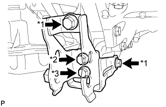
Install the engine mounting control bracket onto the CVT with the 4 bolts.
- Torque:
- 45 N*m { 459 kgf*cm, 33 ft.*lbf }
Tech Tips
*1 (Temporarily tighten) →
*3 (Fully tighten) →
*2 (Fully tighten) →
*1 (Fully tighten)
-
-
INSTALL ENGINE WIRE
-
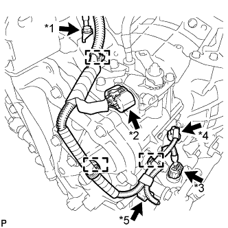
Text in Illustration *1 Bolt *2 Park/Neutral Position Switch Connector *3 Transmission Wire Connector *4 Transmission Revolution Sensor Connector (NT) *5 Transmission Revolution Sensor Connector (NIN) Engage the 3 clamps and install the engine wire to the CVT.
-
Connect the park/neutral position switch connector, the transmission wire connector, and the 2 transmission revolution sensor connectors (NIN, NT).
-
Install the engine wire onto the CVT with the bolt.
- Torque:
- 13 N*m { 133 kgf*cm, 10 ft.*lbf }
-
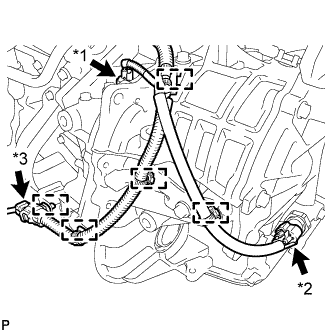
Text in Illustration *1 Transmission Revolution Sensor Connector (NOUT) *2 Oil Pressure Sensor Connector *3 Oxygen Sensor Connector Engage the 5 clamps and install the engine wire to the CVT.
-
Connect the oxygen sensor connector, oil pressure sensor connector and the transmission revolution sensor (NOUT) connector.
-
-
INSTALL WATER BY-PASS HOSE ASSEMBLY
-
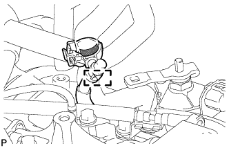
Text in Illustration *1 Rear of Vehicle Connect the 2 water by-pass hoses to the oil cooler with the 2 clamps.
Note
Securely push the hoses over each pipe fitting on the transmission oil cooler until the hoses contact the rib on each pipe fitting.
-
Install the water by-pass hose onto the CVT with the bolt.
- Torque:
- 29 N*m { 296 kgf*cm, 21 ft.*lbf }
-
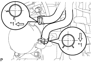
Engage the clamp and install the breather hose to the breather hose clamp.
Text in Illustration 
Paint Mark Tech Tips
-
Install the breather hose clamp so that the top end of it overlaps the painted area.
-
Install the breather hose clamp so that its protuberance is within the painted area.
-
-
-
INSTALL DRIVE SHAFT HEAT INSULATOR BRACKET
-
Install the drive shaft heat insulator bracket onto the engine with the 2 bolts.
- Torque:
- 16 N*m { 166 kgf*cm, 12 ft.*lbf }
-
-
INSTALL ENGINE ASSEMBLY WITH TRANSAXLE
-
Install the engine assembly with transaxle Click here.
-
-
RESET MEMORY (CVT initialization)
Note
Perform Reset Memory (CVT initialization) when replacing the CVT ( Click here).