CONTINUOUSLY VARIABLE TRANSAXLE ASSEMBLY REMOVAL

-
REMOVE ENGINE ASSEMBLY WITH TRANSAXLE
-
REMOVE DRIVE SHAFT HEAT INSULATOR BRACKET
-
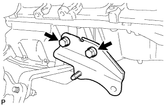
Remove the 2 bolts and the drive shaft heat insulator bracket from the engine.
-
-
DISCONNECT WATER BY-PASS HOSE ASSEMBLY
-
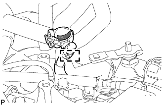
Disengage the clamp and separate the breather hose from the breather hose clamp.
-
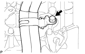
Remove the bolt and separate the water by-pass hose from the continuously variable transaxle assembly.
-
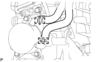
Slide the 2 clamps and separate the 2 water by-pass hoses from the oil cooler.
-
-
DISCONNECT ENGINE WIRE
-
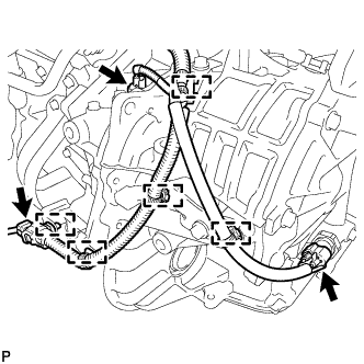
Disconnect the oxygen sensor connector, oil pressure sensor connector and the transmission revolution sensor connector (NOUT).
-
Disengage the 5 clamps and separate the engine wire from the continuously variable transaxle assembly.
-
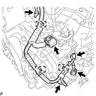
Remove the bolt and separate the engine wire from the continuously variable transaxle assembly.
-
Disconnect the park/neutral position switch connector, transmission wire connector and the 2 transmission revolution sensor connectors (NIN, NT).
-
Disengage the 3 clamps and separate the engine wire from the continuously variable transaxle assembly.
-
-
REMOVE ENGINE MOUNTING CONTROL BRACKET
-
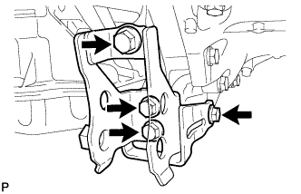
Remove the 4 bolts and the engine mounting control bracket from the continuously variable transaxle assembly.
-
-
REMOVE STARTER ASSEMBLY
-
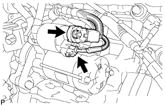
Open the terminal cap.
-
Remove the nut and disconnect terminal 30.
-
Disconnect the connector.
-
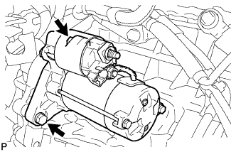
Remove the 2 bolts and the starter assembly.
-
-
REMOVE DRIVE PLATE AND TORQUE CONVERTER SETTING BOLT
-
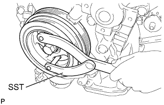
Use SST to hold the crankshaft pulley in place.
- SST
- 09960-10010 ( 09962-01000, 09963-01000 )
-
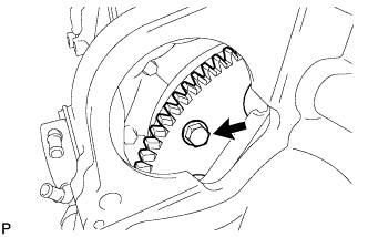
Remove the 6 drive plate and torque converter setting bolts.
-
-
REMOVE CONTINUOUSLY VARIABLE TRANSAXLE ASSEMBLY
-
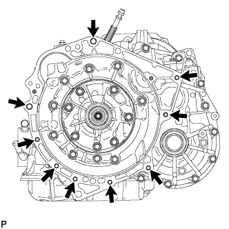
Remove the 9 bolts and the continuously variable transaxle assembly.
Note
Do not twist the continuously variable transaxle assembly when removing it from the engine, because the knock pins could be damaged.
-
-
REMOVE ENGINE MOUNTING STAY LH
-
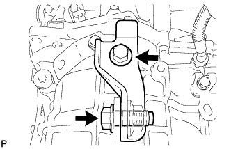
Remove the 2 bolts and the engine mounting stay LH from the continuously variable transaxle assembly and the engine mounting bracket LH.
-
-
REMOVE ENGINE MOUNTING BRACKET LH
-
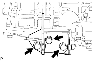
Remove the 3 bolts and the engine mounting bracket LH from the continuously variable transaxle assembly.
-
-
REMOVE NO. 1 TRANSMISSION CONTROL CABLE BRACKET
-
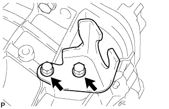
Remove the 2 bolts and the No. 1 transmission control cable bracket from the continuously variable transaxle assembly.
-
-
REMOVE WIRE HARNESS CLAMP BRACKET
-
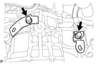
Remove the 2 bolts and the 2 wire harness clamp brackets from the continuously variable transaxle assembly.
-
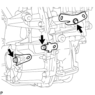
Remove the 3 bolts and the 3 wire harness clamp brackets from the continuously variable transaxle assembly.
-
-
REMOVE TORQUE CONVERTER ASSEMBLY
-
Remove the torque converter assembly from the continuously variable transaxle assembly.
-
-
REMOVE CVT OIL PUMP TYPE T OIL SEAL
Note
-
Do not remove the front oil pump assembly from the continuously variable transaxle assembly main body, as there is the possibility of the entry of dust and foreign matter.
-
Clean the work area, the tools to be used, and other equipment, etc. thoroughly before the operation, as there is the possibility that a continuously variable transaxle assembly malfunction, which could prevent the vehicle from running, could occur if dust or fine foreign matter enters the continuously variable transaxle assembly.
-
Do not use cotton work gloves, cloths, or paper towels, etc. that may produce lint, etc.
-
Perform the operation as quickly as possible, as dust and foreign matter could enter the continuously variable transaxle assembly while the torque convertor is not attached to it.
-
Do not use the air gun until the torque convertor has been installed, as it could cause dust and foreign matter to be stirred up.
-
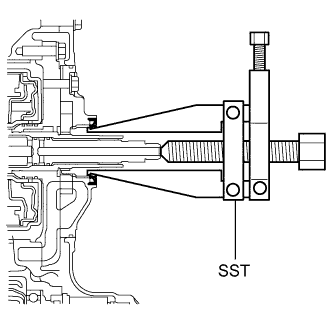
Clean the tips of both the claws of the SST and the center bolt.
-
Using SST, remove the CVT oil pump type T oil seal.
- SST
- 09308-10010
Note
Pay attention to the angle of the claws when opening them, and ensure that they do not come into contact with the oil pump housing, as there is the possibility that metal particles could be produced if they do.
-
-
INSPECT TORQUE CONVERTER
-
Inspect the torque converter one-way clutch.
-
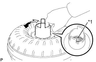
Text in Illustration *1 Splines Lightly rotate the stator by pushing the splines with a finger.
OK Stator rotates smoothly when turned clockwise and there is resistance when it is turned counterclockwise.
-
-
Determine the condition of the torque converter.
-
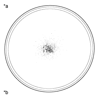
Text in Illustration *1 Sample Showing Maximum Allowable Amount of Particulate in Fluid *2 Actual Size Replace the torque converter if it does not fulfill any of the standard conditions.
Standard conditions *During the stall test or when the shift lever is in N, no metallic sounds are emitted from the torque converter. *The one-way clutch rotates smoothly when turned clockwise and does not rotate when turned counterclockwise. *The amount of particulate in the fluid is not greater than the sample shown in the illustration. Tech Tips
The sample illustration shows approximately 0.025 liters (0.026 US qts, 0.022 Imp. qts) of fluid taken from a removed torque converter clutch.
-
-
Replace the fluid in the torque converter.
-
If the fluid is discolored and/or has a foul odor, stir the fluid in the torque converter thoroughly and drain the fluid with the torque converter facing upward.
-
-
Check that the inside of the oil cooler is clean.
-
When inspecting the torque converter and/or replacing fluid, drain the fluid with the oil cooler installation surface facing downward.
Tech Tips
If there is a large amount of particulate in the fluid, clean the inside of the oil cooler by adding new fluid.
-
If the fluid is cloudy or white, check the oil cooler.
-
-
Check the torque converter installation bolts.
-
All of the installation bolts must be the same length (+/- 0.5 mm (0.0197 in.)) and each must have a spring washer.
-
-
-
INSPECT DRIVE PLATE AND RING GEAR
-
Visually check the drive plate and ring gear.
-
Check the drive plate and ring gear for damage.
Tech Tips
Replace the drive plate and ring gear if it is damaged.
-
-
Inspect runout of drive plate and ring gear.
-
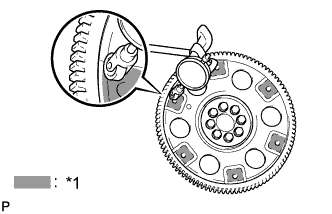
Text in Illustration *1 Measuring Point Set up a dial indicator and measure the runout of the drive plate and ring gear at 6 places along the torque converter installation surface.
Maximum runout 0.30 mm (0.0118 in.) Tech Tips
If the runout exceeds the maximum, replace the drive plate and ring gear.
-
-