SHIFT LEVER INSPECTION
-
INSPECT SHIFT LOCK CONTROL ECU (w/o Entry and Start System)
-
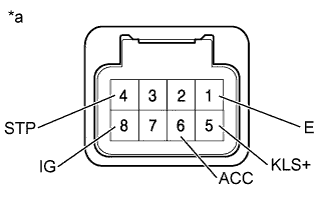
Text in Illustration *a Component with harness connected
(Shift Lock Control ECU)
Measure the voltage according to the value(s) in the table below.
Tech Tips
Do not disconnect the shift lock control ECU connector.
Standard Voltage Tester Connection Switch Condition Specified Condition 4 (STP) - 1 (E) Brake pedal depressed 11 to 14 V Brake pedal released Below 1 V 5 (KLS+) - 1 (E) 1. Ignition switch ACC and shift lever in P Below 1 V 2. Ignition switch ACC and shift lever not in P
(Within approximately 1 second)
7.5 to 10.5 V 3. Ignition switch ACC and shift lever not in P
(After approximately 1 second)
6 to 9 V 6 (ACC) - 1 (E) Ignition switch ACC 11 to 14 V Ignition switch ON 11 to 14 V Ignition switch off Below 1 V 8 (IG) - 1 (E) Ignition switch ON 11 to 14 V Ignition switch off Below 1 V If the result is not as specified and there are no problems with the wire harness, replace the shift lock control ECU.
-
Measure the resistance according to the value(s) in the table below.
Tech Tips
Do not disconnect the shift lock control ECU connector.
Standard Resistance Tester Connection Condition Specified Condition 1 (E) - Body ground When battery voltage not applied Below 1 Ω If the result is not as specified and there are no problems with the wire harness, replace the shift lock control ECU.
-
-
INSPECT SHIFT LOCK CONTROL ECU (w/ Entry and Start System)
-
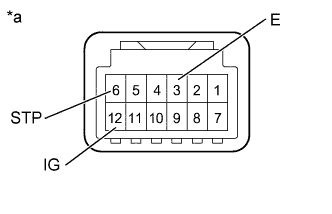
Text in Illustration *a Component with harness connected
(Shift Lock Control ECU)
Measure the voltage according to the value(s) in the table below.
Tech Tips
Do not disconnect the shift lock control ECU connector.
Standard Voltage Tester Connection Switch Condition Specified Condition 6 (STP) - 3 (E) Brake pedal depressed 11 to 14 V Brake pedal released Below 1 V 12 (IG) - 3 (E) Ignition switch ON 11 to 14 V Ignition switch off Below 1 V If the result is not as specified and there are no problems with the wire harness, replace the shift lock control ECU.
-
Measure the resistance according to the value(s) in the table below.
Tech Tips
Do not disconnect the shift lock control ECU connector.
Standard Resistance Tester Connection Condition Specified Condition 3 (E) - Body ground When battery voltage not applied Below 1 Ω If the result is not as specified and there are no problems with the wire harness, replace the shift lock control ECU.
-
-
INSPECT SHIFT LOCK SOLENOID
-
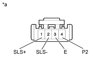
Text in Illustration *a Component without harness connected
(Shift Lock Solenoid)
Disconnect the shift lock solenoid connector of the shift lock ECU.
-
Measure the resistance according to the value(s) in the table below when the shift lever is moved to each position.
Standard Resistance Tester Connection Shift Lever Position Specified Condition 4 (P2) - 3 (E) P 10 kΩ or higher Except P Below 1 Ω If the result is not as specified, replace the shift lock control unit.
-
Measure the resistance according to the value(s) in the table below.
Standard Resistance Tester Connection Condition Specified Condition 1 (SLS+) - 2 (SLS-) When battery voltage not applied 112 Ω If the result is not as specified, replace the shift lock control unit.
-
-
INSPECT TRANSMISSION CONTROL SWITCH (except Multi-mode Automatic Transmission)
-
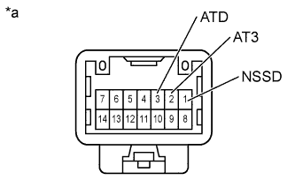
Text in Illustration *a Component without harness connected
(Transmission Control Switch)
Measure the resistance according to the value(s) in the table below when the shift lever is moved to each position.
Standard Resistance Tester Connection Shift Lever Position Specified Condition 1 (NSSD) - 2 (AT3) S or B Below 1 Ω Except S and B 10 kΩ or higher 1 (NSSD) - 3 (ATD) Except S and B Below 1 Ω S or B 10 kΩ or higher If the result is not as specified, replace the shift lock control unit.
-
-
INSPECT TRANSMISSION CONTROL SWITCH (for Multi-mode Automatic Transmission)
-
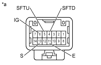
Text in Illustration *a Component without harness connected
(Transmission Control Switch)
Measure the resistance according to the value(s) in the table below when the shift lever is moved to each position.
Standard Resistance Tester Connection Shift Lever Position Specified Condition 4 (SFTD) - 11 (E) "-"
Pressed continuously (Downshift)
Below 1 Ω M 10 kΩ or higher 5 (SFTU) - 11 (E) "+"
Pressed continuously (Upshift)
Below 1 Ω M 10 kΩ or higher 6 (IG) - 13 (S) M, "+" or "-" Below 1 Ω Other than M, "+" and "-" 10 kΩ or higher If the result is not as specified, replace the shift lock control unit.
-