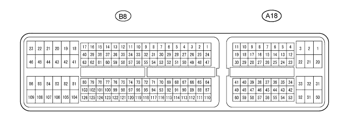
CONTINUOUSLY VARIABLE TRANSAXLE SYSTEM TERMINALS OF ECM
-
ECM
Tech Tips
Each ECM terminal's standard voltage and resistance is shown in the table below.
In the table, first follow the information under "Condition". Look under "Terminal No. (Symbol) " for the terminals to be inspected. The standard voltage and resistance between the terminals is shown under "Specific Condition".
Use the illustration above as a reference for the ECM terminals.
Terminals No. (Symbol) Wiring Color Terminal Description Condition Specified Condition A18-1 (+B2) - B8-105 (E1) L - BR Power supply for IG Ignition switch ON 11 to 14 V A18-2 (+B) - B8-105 (E1) W - BR Power supply for IG Ignition switch ON 11 to 14 V A18-3 (+BM) - B8-105 (E1) R-W - BR Power supply for back-up memory Always 11 to 14 V A18-8 (CANH) - B8-105 (E1) L - BR CAN communication signal Ignition switch ON Pulse generation
(See waveform 1)
A18-9 (CANL) - B8-105 (E1) W - BR CAN communication signal Ignition switch ON Pulse generation
(See waveform 2)
A18-16 (SFTU) - B8-105 (E1)
*1
L - BR Up shift position switch signal Ignition switch ON and shift lever M position 11 to 14 V Ignition switch ON and shift lever "+" position Below 1 V A18-20 (BATT) - B8-105 (E1) B - BR Battery Always 11 to 14 V A18-25 (NSW) - B8-105 (E1) GR - BR Park/Neutral position switch signal Ignition switch ON and shift lever P or N position Below 1 V Ignition switch ON and shift lever other than P and N position 11 to 14 V A18-26 (SDSW) - B8-105 (E1)
*2
L-B - BR Shift lever position switch signal Ignition switch ON and shift lever S or B position 11 to 14 V Ignition switch ON and shift lever other than S and B position Below 1 V A18-36 (STP) - B8-105 (E1) Y - BR Stop light switch signal Brake pedal depressed 7.5 to 14 V Brake pedal released Below 1.5 V A18-44 (MREL) - B8-105 (E1) L-Y - BR Main relay (EFI/ECO) drive signal Ignition switch ON 11 to 14 V A18-47 (D) - B8-105 (E1) L-R - BR D shift position switch signal Ignition switch ON and shift lever D position 11 to 14 V Ignition switch ON and shift lever other than D position Below 1 V A18-48 (STA) - B8-105 (E1) W-R - BR Starter relay drive signal input Cranking 6 V or more A18-51 (SFTD) - B8-105 (E1)
*1
R - BR Down shift position switch signal Ignition switch ON and shift lever M position 11 to 14 V Ignition switch ON and shift lever "-" position Below 1 V B8-39 (B) - B8-105 (E1) B - BR M shift position switch signal (*1) Ignition switch ON and shift lever M position 11 to 14 V Ignition switch ON and shift lever other than M position Below 1 V B shift position switch signal (*2) Ignition switch ON and shift lever B position 11 to 14 V Ignition switch ON and shift lever other than B position Below 1 V B8-54 (SLS+) - B8-53 (SLS-) V - W-L Belt clamping pressure liner solenoid (SLS) signal Engine idling speed Pulse generation
(See waveform 3)
B8-55 (DS2) - B8-105 (E1) P-G - BR Shift control solenoid valve (DS2) signal Accelerator pedal further depressed after driving at a constant vehicle speed with shift lever in D Pulse generation
(See waveform 4)
B8-56 (DS1) - B8-105 (E1) R-L - BR Shift control solenoid valve (DS1) signal Accelerator pedal released while driving with shift lever in D Pulse generation
(See waveform 5)
B8-58 (SL) - B8-105 (E1) P-B - BR Lock-up solenoid (SL) signal Shift lever in N → except D 11 to 14 V → 0 to 1.5 V B8-59 (DSU) - B8-105 (E1) GR-R - BR Lock-up engagement solenoid (DSU) signal Lock-up turned from OFF to ON Pulse generation
(See waveform 6)
B8-70 (THO1) - B8-71 (ETHO) G-Y - B-W CVT fluid temperature sensor signal CVT fluid temperature: 60 to 120°C
(140 to 320°F)
0.2 to 1.0 V B8-73 (PTO) - B8-72 (EPTO) L-B - W-R Secondary pulley pressure sensor signal Engine idling speed and shift lever P position 0.8 to 1.2 B8-76 (R) - B8-105 (E1) R - BR R shift position switch signal Ignition switch ON and shift lever R position 11 to 14 V Ignition switch ON and shift lever other than R position Below 1 V B8-77 (P) - B8-105 (E1) L-R - BR P shift position switch signal Ignition switch ON and shift lever P position 11 to 14 V Ignition switch ON and shift lever other than P position Below 1 V B8-95 (VCPT) - B8-72 (EPTO) V-W - W-R Power supply for secondary pulley pressure sensor signal Ignition switch ON and engine stopped 4.5 to 5.5 V B8-99 (N) - B8-105 (E1) L - BR N shift position switch signal Ignition switch ON and shift lever N position 11 to 14 V Ignition switch ON and shift lever other than N position Below 1 V B8-105 (E1) - Body ground BR - Body ground Ground Always Below 1 Ω B8-122 (NIN+) - B8-100 (NIN-) L - LG Transmission revolution sensor (NIN) signal When driving with shift lever in D, vehicle speed approx. 6 km/h (3.7 mph) and engine speed approx. 700 rpm Pulse generation
(See waveform 7)
B8-124 (NTO) - B8-123 (NTB) V - P Transmission revolution sensor (NT) signal When driving with shift lever in D, vehicle speed approx. 12 km/h (7.5 mph) and engine speed approx. 1150 rpm Pulse generation
(See waveform 8)
B8-125 (NOTO) - B8-101 (NOTB) L - W Transmission revolution sensor (NOUT) signal When driving with shift lever in D, vehicle speed approx. 12 km/h (7.5 mph) and engine speed approx. 1150 rpm Pulse generation
(See waveform 9)
-
*1: for Multi-mode Automatic Transmission
-
*2: except Multi-mode Automatic Transmission
-
Waveform 1 (Reference)
Terminal CANH - E1 Tool setting 1 V/DIV, 10 μs/DIV Vehicle conditions Ignition switch ON -
Waveform 2 (Reference)
Terminal CANL - E1 Tool setting 1 V/DIV, 10 μs/DIV Vehicle conditions Ignition switch ON -
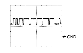
Waveform 3
Terminal SLS+ - SLS- Tool setting 5 V/DIV, 1 ms/DIV Vehicle conditions Engine idling speed -
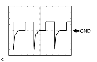
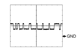
Waveform 4
Terminal DS2 - E1 Tool setting 10 V/DIV, 5 ms/DIV Vehicle conditions Accelerator pedal further depressed after driving at a constant vehicle speed with shift lever in D Tech Tips
Duty ratio increases with downshifts.
-
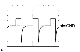
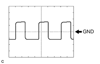
Waveform 5
Terminal DS1 - E1 Tool setting 10 V/DIV, 5 ms/DIV Vehicle conditions Accelerator pedal released while driving with shift lever in D Tech Tips
Duty ratio increases with upshifts.
-
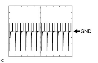
Waveform 6
Terminal DSU - E1 Tool setting 10 V/DIV, 20 ms/DIV Vehicle conditions Lock up turned from OFF to ON Tech Tips
Duty ratio increases to 100% with the lock up ON.
-
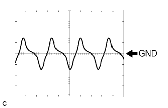
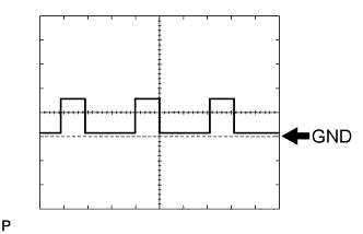
Waveform 7
Terminal NIN+ - NIN- Tool setting 1 V/DIV, 2 ms/DIV Vehicle conditions When driving with shift lever in D, vehicle speed approx. 6 km/h (3.7 mph) and engine speed approx. 700 rpm Tech Tips
The wavelength shortens and the voltage increases as the primary pulley speed increases.
-
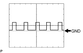
Waveform 8
Terminal NTO - NTB Tool setting 1 V/DIV, 2 ms/DIV Vehicle conditions When driving with shift lever in D, vehicle speed approx. 12 km/h (7.5 mph) and engine speed approx. 1150 rpm Tech Tips
The wavelength shortens as the turbine speed increases.
-
Waveform 9
Terminal NOTO - NOTB Tool setting 1 V/DIV, 2 ms/DIV Vehicle conditions When driving with shift lever in D, vehicle speed approx. 12 km/h (7.5 mph) and engine speed approx. 1150 rpm Tech Tips
The wavelength shortens as the secondary pulley speed increases.
-