CONTINUOUSLY VARIABLE TRANSAXLE SYSTEM, Diagnostic DTC:P2763, P2764
| DTC Code | DTC Name |
|---|---|
| P2763 | Torque Converter Clutch Pressure Control Solenoid Control Circuit High (Shift Solenoid Valve DSU) |
| P2764 | Torque Converter Clutch Pressure Control Solenoid Control Circuit Low (Shift Solenoid Valve DSU) |
DESCRIPTION
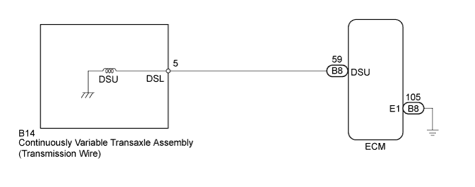
The ECM controls the signal to the lock-up engagement solenoid DSU and performs lock-up clutch pressure control in response to the input torque value.
| DTC No. | DTC Detection Condition
|
Trouble Area |
|---|---|---|
| P2763 |
|
|
| P2764 |
|
|
MONITOR DESCRIPTION
This DTC indicates an open or short in the lock-up engagement solenoid DSU circuit. The ECM controls the gearshift by turning the lock-up engagement solenoid DSU (on/off). When there is an open or short circuit in engagement solenoid valve circuit, the ECM detects the problem, illuminates the MIL and stores the DTC.
WIRING DIAGRAM
INSPECTION PROCEDURE
PROCEDURE
-
INSPECT CONTINUOUSLY VARIABLE TRANSAXLE ASSEMBLY (LOCK-UP ENGAGEMENT SOLENOID DSU)
-
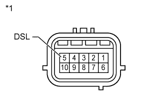
Text in Illustration *1 Component without wire harness connected:
(Continuously Variable Transaxle Assembly
(Transmission wire))
Disconnect the transmission wire connector from the transaxle.
-
Measure the resistance according to the value(s) in the table below.
Standard Resistance Tester Connection Condition Specified Condition 5 (DSL) - Body ground 20°C (68°F) 11 to 15 Ω
NG 
REPLACE CONTINUOUSLY VARIABLE TRANSAXLE ASSEMBLY Click here
OK 
-
-
CHECK HARNESS AND CONNECTOR (TRANSMISSION WIRE - ECM)
-
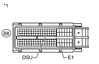
Text in Illustration *1 Front view of wire harness connector:
(to ECM)
Connect the transmission wire connector to the transaxle.
-
Disconnect the ECM connector.
-
Measure the resistance according to the value(s) in the table below.
Standard Resistance Tester Connection Condition Specified Condition B8-59 (DSU) - B8-105 (E1) 20°C (68°F) 11 to 15 Ω
NG 
REPAIR OR REPLACE HARNESS OR CONNECTOR
OK
-
-
REPLACE ECM
-
Replace the ECM Click here.
NEXT
-
-
PERFORM INITIALIZATION
-
Perform the initialization Click here.
-
Check for DTCs again Click here.
NEXT 
END
-
-
REPLACE CONTINUOUSLY VARIABLE TRANSAXLE ASSEMBLY
-
Replace the continuously variable transaxle assembly Click here.
NEXT
-
-
PERFORM INITIALIZATION
-
Perform the initialization Click here.
-
Check for DTCs again Click here.
NEXT
END
-