CONTINUOUSLY VARIABLE TRANSAXLE SYSTEM, Diagnostic DTC:P1586
| DTC Code | DTC Name |
|---|---|
| P1586 | Acceleration Sensor Malfunction |
DESCRIPTION
The ECM determines the vehicle inclination based on a signal from the yaw rate and acceleration sensor to perform neutral control. If a malfunction is determined in the yaw rate and acceleration sensor based on a malfunction signal from the brake actuator assembly, the ECM cancels neutral control as a fail-safe function.
Tech Tips
-
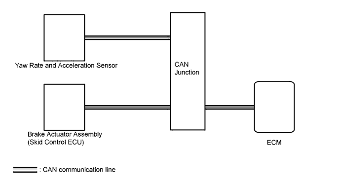
The ECM receives a yaw rate and acceleration sensor signal from the brake actuator assembly via CAN communication.
If a CAN communication DTC is output, perform troubleshooting for that DTC first.
| DTC No. | DTC Detection Condition
|
Trouble Area |
|---|---|---|
| P1586 |
|
|
|
WIRING DIAGRAM
INSPECTION PROCEDURE
PROCEDURE
-
CHECK DTC OUTPUT (CAN COMMUNICATION SYSTEM)
-
Check for DTCs of the CAN communication system Click here.
Result Result Proceed to DTCs are not output A DTCs are output B
B 
GO TO CAN COMMUNICATION SYSTEM Click here
A 
-
-
CHECK OTHER DTC OUTPUT (IN ADDITION TO DTC P1586)
-
Clear the DTCs Click here.
-
Perform a road test where the vehicle is driven at 30 km/ h (18 mph) or more, the brakes are applied at least 16 times and the vehicle is finally stopped.
-
Connect the intelligent tester to the DLC3.
-
Turn the ignition switch to ON.
-
Turn the tester on.
-
Enter the following menus: Powertrain / Engine and ECT / DTC / Current or Pending.
-
Read the DTCs using the tester.
Result Result Proceed to Only P1586 is output A P1586 and other DTCs are output B Tech Tips
If any other codes besides DTC P1586 are output, perform troubleshooting for those DTCs first.
B
GO TO DTC CHART Click here
A
-
-
READ VALUE USING INTELLIGENT TESTER
-
Connect the intelligent tester to the DLC3.
-
Turn the ignition switch to ON.
-
Turn the tester on.
-
Enter the following menus: Powertrain / Engine and ECT / Data List.
-
In accordance with the display on the tester, read the Data List.
Tester Display Measurement Item/Range Normal Condition Diagnostic Note G sensor Converted output voltage of yaw rate and acceleration sensor/
min.: 0 V
max.: 5 V
Displays converted voltage of yaw rate and acceleration sensor
-
Vehicle on level ground: 2.31 V to 2.69 V
-
Decelerating: 1.88 V to (2.5) V
-
Accelerating: (2.5) V to 3.11 V
-
G sensor malfunction: set to 1.87 V
-
Communication malfunction: set to 1.87 V
- Result Result Proceed to Data display is not within Normal Condition range A Data display is within Normal Condition range B -
B
REPLACE BRAKE ACTUATOR ASSEMBLY Click here
A
-
-
REPLACE YAW RATE AND ACCELERATION SENSOR
-
Replace yaw rate and acceleration sensor Click here.
NEXT
-
-
PERFORM INITIALIZATION
-
Perform the initialization Click here.
-
Check for DTCs again Click here.
NEXT 
END
-