CLUTCH MASTER CYLINDER (for LHD) INSTALLATION

-
INSTALL CLUTCH MASTER CYLINDER ASSEMBLY
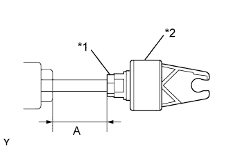
Text in Illustration *1 Adjusting nut *2 Push rod clevis
-
Tighten the adjusting nut and adjust the dimension A to be the same as the measured dimension A.
- Torque:
- 12 N*m { 120 kgf*cm, 9 ft.*lbf }
-
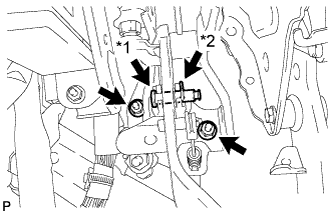
Text in Illustration *1 Push rod clevis pin *2 Clip Install the clutch master cylinder with the 2 nuts.
- Torque:
- 13 N*m { 129 kgf*cm, 9 ft.*lbf }
-
Apply MP grease to the contact surface of the push rod clevis pin.
-
Connect the clevis to the clutch pedal with the push rod clevis pin.
Tech Tips
Install the push rod clevis pin from the left side of the vehicle.
-
Install the new clip onto the push rod clevis pin.
-
Install the clutch pedal spring to the push rod clevis pin.
-
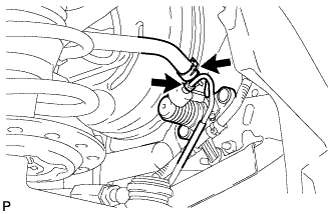
Using a union nut wrench 10 mm, connect the flexible hose tube.
- Torque:
- 15 N*m { 155 kgf*cm, 11 ft.*lbf }
Note
Use the formula to calculate special torque values for situations where union nut wrench is combined with a torque wrench Click here.
-
Connect the clutch reservoir tube with the clip to the clutch master cylinder assembly.
-
-
BLEED CLUTCH LINE
-
Bleed the clutch line Click here.
-
-
INSPECT AND ADJUST CLUTCH PEDAL SUB-ASSEMBLY
-
Pull back the floor carpet.
-
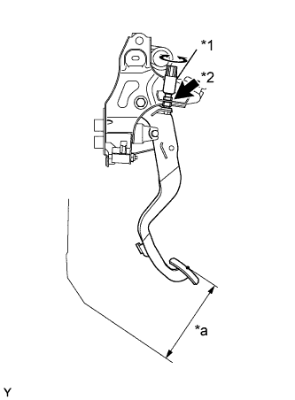
Text in Illustration *1 Clutch switch assembly *2 Adjust nut *a Clutch pedal height Check that the pedal height is correct.
Pedal height from floor for 1KR-FE, 1NR-FE 123.9 to 133.9 mm (4.878 to 5.272 in.) for 1ND-TV 136.7 to 146.7 mm (5.382 to 5.776 in.) -
If the pedal height is not as specified, adjust it as follows.
-
Loosen the adjusting nut and turn the clutch pedal switch until the correct height is obtained.
-
Tighten the adjusting nut.
- Torque:
- 16 N*m { 160 kgf*cm, 12 ft.*lbf }
-
-
-
INSTALL KNEE AIR BAG ASSEMBLY
-
Install the knee air bag assembly Click here.
-