STOP AND START SYSTEM, Diagnostic DTC:P2531
| DTC Code | DTC Name |
|---|---|
| P2531 | Ignition Switch Run Position Circuit Low |
DESCRIPTION
The EFI relay turns off approximately 3 to 4 seconds after the ignition switch is turned off, shutting off the power supply to the engine stop and start ECU. Therefore, if the ECM is in the IG-ON state, the engine stop and start ECU should also be in the IG-ON state.
If ignition switch signals are not detected for a certain time period even while the ignition switch is ON, it is determined that there is an open in the ignition switch signal circuit and this DTC will be stored.
| DTC No. | DTC Detection Condition | Trouble Area |
|---|---|---|
| P2531 | Both of the following conditions continue for 60 seconds or more (1 trip detection logic):
|
|
Tech Tips
DTCs for the Stop and Start system are not cleared even if the malfunction has been repaired. After repairing the malfunction, be sure to clear the DTCs Click here.
-
After troubleshooting, perform the following steps to recheck for DTCs and check if the Stop and Start system operates normally.
Tech Tips
-
If the ECM learned values have been cleared by disconnecting the battery or for another reason, Stop and Start system control will be prohibited until ECM learning completes.
-
Allow the engine to idle for 3 minutes after the engine warms up and check that the engine speed is within 50 rpm of the target idle speed.
-
Connect the intelligent tester to the DLC3.
-
Clear the DTCs Click here.
-
Start the engine and warm it up.
-
Drive the vehicle at 20 km/h (12.4 mph) or more and stop the vehicle to allow the engine to stop due to Stop and Start system control.
-
Wait for at least 90 seconds. Depress the clutch pedal to allow the engine to restart and idle for at least 10 seconds.
Tech Tips
Depending on the vehicle conditions, the engine may restart in less than 90 seconds.
-
Check that no DTCs are output Click here.
-
-
Check if the Stop and Start system operates normally.
Tech Tips
If the battery terminal has been disconnected, the ECO OFF indicator will be illuminated. In this case, drive the vehicle for 15 to 40 minutes to turn off the indicator.
-
Warm up the engine.
-
Turn the air conditioning system off.
-
Drive the vehicle at 7 km/h (4.3 mph) or more.
-
Stop the vehicle. Move the shift lever to neutral and release the clutch pedal.
-
Check that the engine stops.
-
Depress the clutch pedal and check that the engine restarts.
-
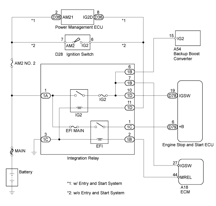
WIRING DIAGRAM
INSPECTION PROCEDURE
Note
-
If the engine stop and start ECU is being replaced, register the previously recorded number of starter operations into the new engine stop and start ECU Click here.
-
After the engine stop and start ECU is replaced or after an air conditioner kit is installed, clear the A/C information stored in the engine stop and start ECU Click here.
-
Inspect the fuses for circuits related to this system before performing the following inspection procedure.
PROCEDURE
-
READ VALUE USING INTELLIGENT TESTER (IG SWITCH SIGNAL)
-
Connect the intelligent tester to the DLC3.
-
Turn the ignition switch to ON.
-
Turn the tester on.
-
Enter the following menus: Powertrain / Stop and Start / Data List / IG Switch.
-
Read the value displayed on the tester.
Result Result Proceed to ON A OFF B
B 
CHECK HARNESS AND CONNECTOR (ENGINE STOP AND START ECU - INTEGRATION RELAY) Click here
A 
USE SIMULATION METHOD TO CHECK Click here
-
-
CHECK HARNESS AND CONNECTOR (ENGINE STOP AND START ECU - INTEGRATION RELAY)
-
Disconnect the engine stop and start ECU connector.
-
Remove the integration relay from the No. 1 engine room relay block.
-
Disconnect the integration relay connector.
-
Measure the resistance according to the value(s) in the table below.
Standard Resistance Tester Connection Condition Specified Condition D78-19 (IGSW) - 1D-10 (IG2 Relay) Always Below 1 Ω D78-19 (IGSW) or 1D-10 (IG2 Relay) - Body ground Always 10 kΩ or higher -
Reconnect the engine stop and start ECU connector.
-
Reconnect the integration relay connector.
-
Reinstall the integration relay.
NG 
REPAIR OR REPLACE HARNESS OR CONNECTOR
OK 
-
-
INSPECT INTEGRATION NO.1 RELAY (IG2 RELAY)
-
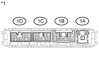
Text in Illustration *1 Component without harness connected:
(Integration Relay)
Remove the integration relay from the No. 1 engine room relay block.
-
Disconnect the integration relay connector.
-
Measure the resistance according to the value(s) in the table below.
Standard Resistance Tester Connection Condition Specified Condition 1A-1 - 1D-10 Battery voltage not applied 10 kΩ or higher Battery voltage applied to terminals 1D-11 and 1C-3 Below 1 Ω -
Reconnect the integration relay connector.
-
Reinstall the integration relay.
NG
REPLACE INTEGRATION NO.1 RELAY (IG2 RELAY)
OK
-
-
CHECK HARNESS AND CONNECTOR (INTEGRATION RELAY - BATTERY)
-
Disconnect the cable from the negative (-) battery terminal.
-
Disconnect the cable from the positive (+) battery terminal.
-
Remove the integration relay from the No. 1 engine room relay block.
-
Disconnect the integration relay connector.
-
Measure the resistance according to the value(s) in the table below.
Standard Resistance Tester Connection Condition Specified Condition 1A-1 - Battery positive terminal Always Below 1 Ω 1A-1 or Battery positive terminal - Body ground Always 10 kΩ or higher -
Reconnect the integration relay connector.
-
Reinstall the integration relay.
-
Reconnect the cable to the positive (+) battery terminal.
-
Reconnect the cable to the negative (-) battery terminal.
NG
REPAIR OR REPLACE HARNESS OR CONNECTOR
OK
-
-
CHECK HARNESS AND CONNECTOR (INTEGRATION RELAY - BODY GROUND)
-
Remove the integration relay from the No. 1 engine room relay block.
-
Disconnect the integration relay connector.
-
Measure the resistance according to the value(s) in the table below.
Standard Resistance Tester Connection Condition Specified Condition 1C-3 - Body ground Always Below 1 Ω Result Result Proceed to NG A OK (w/o Entry and Start System) B OK (w/ Entry and Start System) C -
Reconnect the integration relay connector.
-
Reinstall the integration relay.
B
CHECK HARNESS AND CONNECTOR (INTEGRATION RELAY - IGNITION SWITCH ASSEMBLY) Click here
C
CHECK HARNESS AND CONNECTOR (INTEGRATION RELAY - POWER MANAGEMENT ECU) Click here
A
REPAIR OR REPLACE HARNESS OR CONNECTOR
-
-
CHECK HARNESS AND CONNECTOR (INTEGRATION RELAY - IGNITION SWITCH ASSEMBLY)
-
Remove the integration relay from the No. 1 engine room relay block.
-
Disconnect the integration relay connector.
-
Disconnect the ignition switch connector.
-
Measure the resistance according to the value(s) in the table below.
Standard Resistance Tester Connection Condition Specified Condition 1D-11 - D28-6 (IG2) Always Below 1 Ω 1D-11 or D28-6 (IG2) - Body ground Always 10 kΩ or higher -
Reconnect the integration relay connector.
-
Reinstall the integration relay.
-
Reconnect the ignition switch assembly connector.
NG
REPAIR OR REPLACE HARNESS OR CONNECTOR
OK
-
-
INSPECT IGNITION SWITCH ASSEMBLY
-
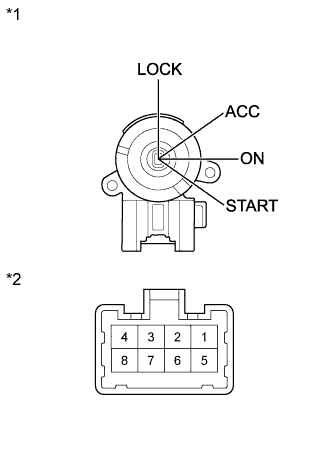
Text in Illustration *1 Ignition Switch Position *2 Component without harness connected:
(Ignition Switch)
Remove the ignition switch.
-
Measure the resistance according to the value(s) in the table below.
Standard Resistance Tester Connection Switch Condition Specified Condition All Terminals LOCK 10 kΩ or higher 2 - 3 ACC Below 1 Ω 2 - 3 - 4, 6 - 7 ON 1 - 2 - 4, 6 - 7 - 8 START Result Result Proceed to NG A OK B -
Reinstall the ignition switch.
B
CHECK HARNESS AND CONNECTOR (ENGINE STOP AND START ECU - INTEGRATION RELAY) Click here
A
REPLACE IGNITION SWITCH ASSEMBLY Click here
-
-
CHECK HARNESS AND CONNECTOR (INTEGRATION RELAY - POWER MANAGEMENT ECU)
-
Remove the integration relay from the No. 1 engine room relay block.
-
Disconnect the integration relay connector.
-
Disconnect the D36 power management ECU connector.
-
Measure the resistance according to the value(s) in the table below.
Standard Resistance Tester Connection Condition Specified Condition 1D-11 - D36-8 (IG2D) Always Below 1 Ω 1D-11 or D36-8 (IG2D) - Body ground Always 10 kΩ or higher -
Reconnect the integration relay connector.
-
Reinstall the integration relay.
-
Reconnect the power management ECU connector.
NG
REPAIR OR REPLACE ENTRY AND START SYSTEM (IG2D CIRCUIT) Click here
OK
-
-
CHECK HARNESS AND CONNECTOR (ENGINE STOP AND START ECU - INTEGRATION RELAY)
-
Disconnect the engine stop and start ECU connector.
-
Remove the integration relay from the No. 1 engine room relay block.
-
Disconnect the integration relay connector.
-
Measure the resistance according to the value(s) in the table below.
Standard Resistance Tester Connection Condition Specified Condition D79-6 (+B) - 1C-1 (EFI RELAY) Always Below 1 Ω D79-6 (+B) or 1C-1 (EFI RELAY) - Body ground Always 10 kΩ or higher -
Reconnect the engine stop and start ECU connector.
-
Reconnect the integration relay connector.
-
Reinstall the integration relay.
NG
REPAIR OR REPLACE HARNESS OR CONNECTOR
OK
-
-
INSPECT ECM (IGSW VOLTAGE)
-
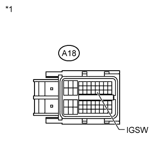
Text in Illustration *1 Front view of wire harness connector:
(to ECM)
Disconnect the ECM connector.
-
Turn the ignition switch to ON.
-
Measure the voltage according to the value(s) in the table below.
Standard Voltage Tester Connection Switch Condition Specified Condition A18-27 (IGSW) - Body ground Ignition switch ON 11 to 14 V -
Reconnect the ECM connector.
NG
CHECK HARNESS OR CONNECTOR (IGSW CIRCUIT FOR ECM) Click here
OK
-
-
INSPECT INTEGRATION NO.1 RELAY (EFI RELAY)
-
Text in Illustration *1 Component without harness connected:
(Integration Relay)
Remove the integration relay from the No. 1 engine room relay block.
-
Disconnect the integration relay connector.
-
Measure the resistance according to the value(s) in the table below.
Standard Resistance Tester Connection Condition Specified Condition 1C-1 - 1A-1 Battery voltage not applied 10 kΩ or higher Battery voltage applied to terminals 1B-2 and 1C-3 Below 1 Ω -
Reconnect the integration relay connector.
-
Reinstall the integration relay.
NG
REPLACE INTEGRATION NO.1 RELAY (EFI RELAY)
OK
-
-
CHECK HARNESS AND CONNECTOR (INTEGRATION RELAY - ECM)
Tech Tips
If the data in the ECM can be read using the intelligent tester even when 30 seconds or more have elapsed after the ignition switch is turned off, there may be a malfunction in the EFI relay circuit.
-
Remove the integration relay from the No. 1 engine room relay block.
-
Disconnect the integration relay connector.
-
Disconnect the ECM connector.
-
Measure the resistance according to the value(s) in the table below.
Standard Resistance Tester Connection Condition Specified Condition 1B-2 - A18-44 (MREL) Always Below 1 Ω 1B-2 or A18-44 (MREL) - Body ground Always 10 kΩ or higher -
Reconnect the ECM connector.
-
Reconnect the integration relay connector.
-
Reinstall the integration relay.
NG
REPAIR OR REPLACE HARNESS OR CONNECTOR
OK
-
-
CHECK HARNESS AND CONNECTOR (INTEGRATION RELAY - BATTERY)
-
Disconnect the cable from the negative (-) battery terminal.
-
Disconnect the cable from the positive (+) battery terminal.
-
Remove the integration relay from the No. 1 engine room relay block.
-
Disconnect the integration relay connector.
-
Measure the resistance according to the value(s) in the table below.
Standard Resistance Tester Connection Condition Specified Condition 1A-1 - Battery positive terminal Always Below 1 Ω 1A-1 or Battery positive terminal - Body ground Always 10 kΩ or higher -
Reconnect the integration relay connector.
-
Reinstall the integration relay.
-
Reconnect the cable to the positive (+) battery terminal.
-
Reconnect the cable to the negative (-) battery terminal.
NG
REPAIR OR REPLACE HARNESS OR CONNECTOR
OK
-
-
CHECK HARNESS AND CONNECTOR (INTEGRATION RELAY - BODY GROUND)
-
Remove the integration relay from the No. 1 engine room relay block.
-
Disconnect the integration relay connector.
-
Measure the resistance according to the value(s) in the table below.
Standard Resistance Tester Connection Condition Specified Condition 1C-3 - Body ground Always Below 1 Ω -
Reconnect the integration relay connector.
-
Reinstall the integration relay.
NG
REPAIR OR REPLACE HARNESS OR CONNECTOR
OK
REPLACE ENGINE STOP AND START ECU Click here
-