STOP AND START SYSTEM, Diagnostic DTC:P323B
| DTC Code | DTC Name |
|---|---|
| P323B | Backup Boost Converter |
DESCRIPTION
The backup boost converter supplements battery voltage to help prevent it from dropping when the engine is restarted during Stop and Start system control. This is done to prevent some electrical systems, such as the audio system, from being disabled due to low power supply voltage.
The engine stop and start ECU monitors for low battery voltage according to the conditions for Stop and Start system control and starter ON/OFF signals. If the voltage drops below a threshold, the ECU requests the backup boost converter to boost battery voltage via the DDON terminal.
The input voltage present when the DDON terminal switches from standby mode to boosting mode is set as the target voltage. If the voltage is below 11 V when switching to boosting mode, the target voltage will be set to 11 V.
If the backup boost converter fails to maintain a certain level of battery voltage when the engine is started due to Stop and Start system control, the error is sent to the engine stop and start ECU by duty signal. The engine stop and start ECU will then store DTC P323B.
The backup boost converter has a control circuit and relay for each electrical system it supplies, such as the meter, audio, and air conditioning systems. If a malfunction occurs in a circuit connected with the backup boost converter, the relay opens to protect the circuit (the relay remains open until the next trip).
If a relay opens, power supply to the circuit will be shut off, disabling the respective systems on that circuit.
If a malfunction occurs in the Stop and Start system, the ECO indicator light blinks (the MIL does not come on). However, the ECO indicator light blinks only during the trip in which the malfunction is detected while the engine is stopped due to Stop and Start system.
| DTC No. | DTC Detection Condition | Trouble Area |
|---|---|---|
| P323B | Any of the following conditions is met (1 trip detection logic):
|
|
-
After troubleshooting, perform the following steps to recheck for DTCs, check the battery voltage, and confirm that the Stop and Start system operates normally.
Tech Tips
-
If the ECM learned values have been cleared by disconnecting the battery or for another reason, Stop and Start system control will be prohibited until ECM learning completes.
-
Allow the engine to idle for 3 minutes after the engine warms up and check that the engine speed is within 50 rpm of the target idle speed.
-
Check if the battery has become weak.
-
Connect the intelligent tester to the DLC3.
-
Clear the DTCs Click here.
-
Warm up the engine until the engine coolant temperature reaches 75°C (167°F) (if the battery terminal has been disconnected, engine system learning will be necessary).
-
Drive the vehicle at 20 km/h (12.4 mph) or more. Run the engine at idle for 3 minutes or more with the air conditioning system off.
-
Stop the vehicle. Move the shift lever to neutral and release the clutch pedal. Check that the engine stops due to Stop and Start system control.
Tech Tips
-
The air conditioning system is off.
-
The engine hood is closed.
-
The driver door is closed.
-
-
Depress the clutch pedal to allow the engine to restart due to Stop and Start system control.
-
Drive the vehicle at 20 km/h (12.4 mph) or more and stop the vehicle (check that the engine stops due to Stop and Start system control).
-
With the engine stopped due to Stop and Start system control, wait for at least 90 seconds. Depress the clutch pedal to restart the engine and allow it to idle for 10 seconds or more.
Tech Tips
Depending on the vehicle conditions, the engine may restart in less than 90 seconds.
-
Check that no DTCs are output Click here.
-
-
Check if the Stop and Start system operates normally.
Tech Tips
If the battery terminal has been disconnected, the ECO OFF indicator will be illuminated. In this case, drive the vehicle for 15 to 40 minutes to turn off the indicator.
-
Warm up the engine.
-
Turn the air conditioning system off.
-
Drive the vehicle at 7 km/h (4.3 mph) or more.
-
Stop the vehicle. Move the shift lever to neutral and release the clutch pedal.
-
Check that the engine stops.
-
Depress the clutch pedal and check that the engine restarts.
-
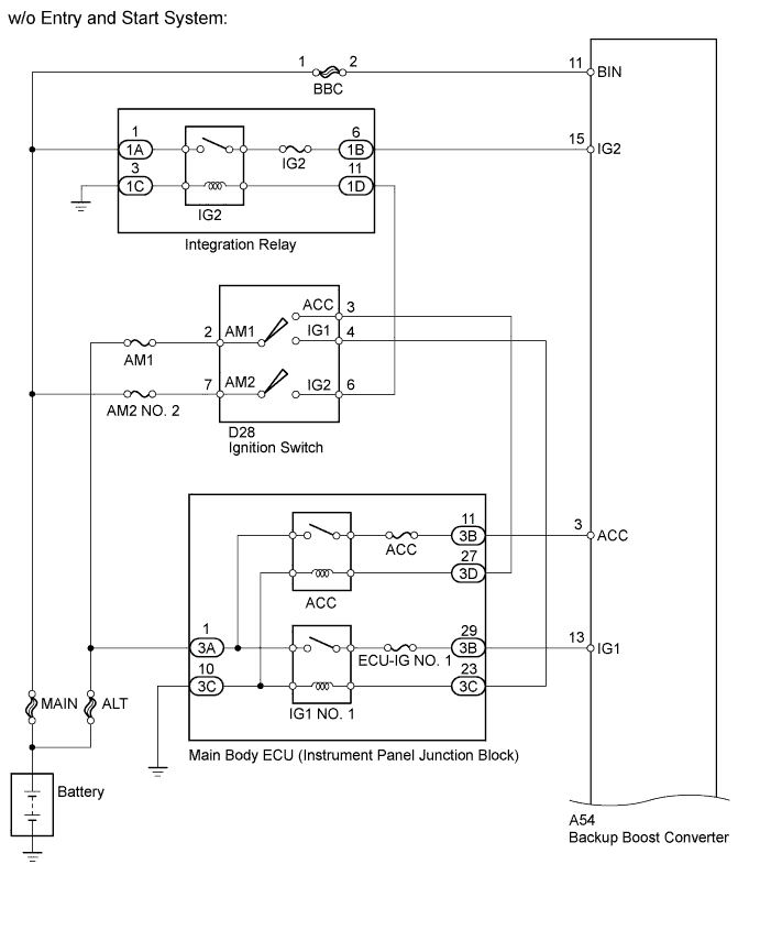
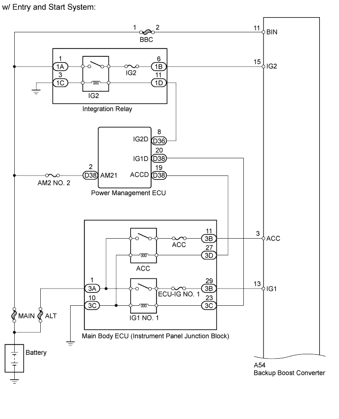
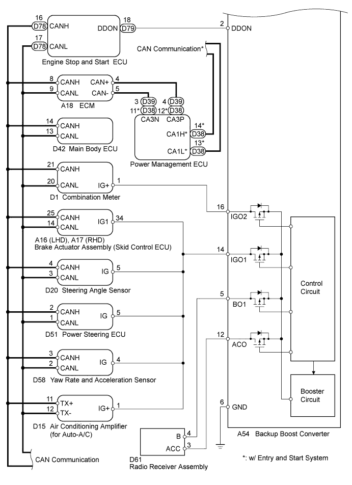
WIRING DIAGRAM
INSPECTION PROCEDURE
Note
Inspect the fuses for circuits related to this system before performing the following inspection procedure.
PROCEDURE
-
READ VALUE USING INTELLIGENT TESTER (STATE OF BBC)
-
Connect the intelligent tester to the DLC3.
-
Turn the ignition switch to ON.
-
Check the "State of BBC" item of the freeze frame data.
Result Result Proceed to Duty Err A Cycle Err A Low Vol B Overvol C Tech Tips
The details of the tester displays are shown below.
Tester Display Details Duty Err Inappropriate DDON duty value is detected Cycle Err DDON duty cycle deviates beyond the allowable range Low Vol A decrease in the voltage of the control IC power source within the backup boost converter is detected when ignition switch is turned to ON Overvol When the ignition switch is turned to ON:
-
Overvoltage is detected at the control IC power source within the backup boost converter
-
Overheating is detected at the control IC power source within the backup boost converter
When boosting:
-
Error is detected in the feedback circuit in the backup boost converter
-
Too high or low output voltage
-
B 
CHECK BATTERY (BATTERY CONDITION) Click here
C
CHECK HARNESS AND CONNECTOR (ENGINE STOP AND START ECU - BACKUP BOOST CONVERTER) Click here
A 
-
-
REPLACE BACKUP BOOST CONVERTER
-
Replace the backup boost converter Click here.
-
Clear the DTCs Click here.
NEXT
-
-
CONFIRM DTC (P323B IS NOT OUTPUT)
-
Warm up the engine until the engine coolant temperature reaches 75°C (167°F).
-
Run the engine at idle 3 minutes or more with the air conditioning system off.
-
Drive the vehicle at 20 km/h (12.4 mph) or more.
Tech Tips
If the battery terminal has been disconnected, the ECO OFF indicator will be illuminated. In this case, drive the vehicle for 15 to 40 minutes to turn off the indicator.
-
Stop the vehicle and allow Stop and Start system control to occur.
Tech Tips
-
The air conditioning system is off.
-
The engine hood is closed.
-
The driver door is closed.
-
-
Restart the engine using Stop and Start system control.
-
Stop the engine.
-
Connect the intelligent tester to the DLC3.
-
Turn the ignition switch to ON.
-
Check for DTCs Click here.
OK No DTC output.
NEXT 
END
-
-
CHECK BATTERY (BATTERY CONDITION)
-
Check the battery condition Click here.
-
Crank the engine using the ignition switch and check if the engine cranks normally.
OK Engine cranks normally. Tech Tips
If the engine does not crank normally, charge the battery and check again. If the engine does not crank normally even after the battery has been charged, replace the battery.
NG 
CHECK BATTERY CHARGING SYSTEM Click here
OK
-
-
CHECK CONNECTOR (BACKUP BOOST CONVERTER CONNECTOR CONDITION)
-
Check if the connector of the backup boost converter is connected securely.
Tech Tips
If any terminal of the backup boost converter connector is not connected securely, CAN communication DTCs for the corresponding systems may also be output.
Backup Boost Converter Internal Circuit CAN Communication DTC IGO1 circuit U0100, U0121, U0131, U0140, U0164 IGO2 circuit U0155 OK The connector is securely connected.
NG
CONNECT CONNECTOR CORRECTLY
OK
-
-
INSPECT FUSE (BBC FUSE)
-
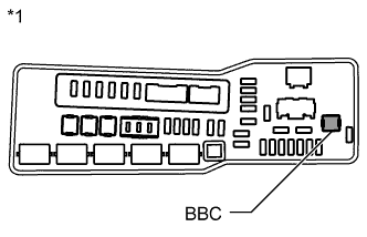
Text in Illustration *1 No. 1 Engine Room Relay Block: Remove the BBC fuse from the No. 1 engine room relay block.
-
Measure the resistance according to the value(s) in the table below.
Standard Resistance Tester Connection Condition Specified Condition BBC fuse Always Below 1 Ω -
Reinstall the BBC fuse.
Tech Tips
If the BBC fuse is blown, related systems, such as ABS/VSC, EPS, meter, audio and air conditioning systems will be disabled.
NG
CHECK FOR SHORT IN ALL HARNESSES AND CONNECTORS CONNECTED TO FUSE AND REPLACE FUSE
OK
-
-
CHECK HARNESS AND CONNECTOR (ENGINE STOP AND START ECU - BACKUP BOOST CONVERTER)
-
Disconnect the engine stop and start ECU connector.
-
Disconnect the backup boost converter connector.
-
Measure the resistance according to the value(s) in the table below.
Standard Resistance Tester Connection Condition Specified Condition D79-18 (DDON) - A54-2 (DDON) Always Below 1 Ω D79-18 (DDON) or A54-2 (DDON) - Body ground Always 10 kΩ or higher -
Reconnect the engine stop and start ECU connector and backup boost converter connector.
NG
REPAIR OR REPLACE HARNESS OR CONNECTOR
OK
-
-
CHECK HARNESS AND CONNECTOR (BACKUP BOOST CONVERTER - ENGINE ROOM RELAY BLOCK)
-
Remove the BBC fuse from the No. 1 engine room relay block.
-
Disconnect the backup boost converter connector.
-
Measure the resistance according to the value(s) in the table below.
Standard Resistance Tester Connection Condition Specified Condition 2 (BBC fuse) - A54-11 (BIN) Always Below 1 Ω 2 (BBC fuse) or A54-11 (BIN) - Body ground Always 10 kΩ or higher -
Reconnect the backup boost converter connector.
-
Reinstall the BBC fuse.
NG
REPAIR OR REPLACE HARNESS OR CONNECTOR
OK
REPLACE BACKUP BOOST CONVERTER Click here
-