STOP AND START SYSTEM, Diagnostic DTC:P1862
| DTC Code | DTC Name |
|---|---|
| P1862 | Clutch Control System 2 |
DESCRIPTION
There are 2 clutch pedal switches for the clutch pedal. The clutch switch (upper) is used for stopping and restarting the engine due to Stop and Start system control. In the Stop and Start system control, the clutch start switch (lower) is used only when the clutch switch (upper) is stuck on or the fail-safe function is activated.
| DTC No. | DTC Detection Condition | Trouble Area |
|---|---|---|
| P1862 | Both of the following conditions continue for 0.5 seconds or more (1 trip detection logic):
|
|
Tech Tips
DTCs for the Stop and Start system are not cleared even if the malfunction has been repaired. After repairing the malfunction, be sure to clear the DTCs Click here.
-
After troubleshooting, perform the following steps to recheck for DTCs and check if the Stop and Start system operates normally.
Tech Tips
-
If the ECM learned values have been cleared by disconnecting the battery or for another reason, Stop and Start system control will be prohibited until ECM learning completes.
-
Allow the engine to idle for 3 minutes after the engine warms up and check that the engine speed is within 50 rpm of the target idle speed.
-
Connect the intelligent tester to the DLC3.
-
Clear the DTCs Click here.
-
Start the engine.
-
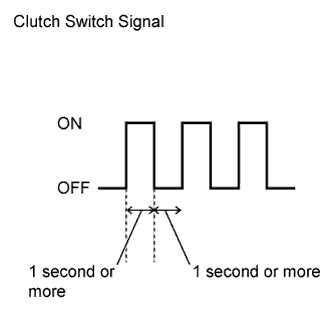
Fully depress the clutch pedal for 1 second or more. Release the clutch pedal and wait for at least 1 second.
-
Repeat the previous step 3 times.
-
Check that no DTCs are output Click here.
-
-
Check if the Stop and Start system operates normally.
Tech Tips
If the battery terminal has been disconnected, the ECO OFF indicator will be illuminated. In this case, drive the vehicle for 15 to 40 minutes to turn off the indicator.
-
Warm up the engine.
-
Turn the air conditioning system off.
-
Drive the vehicle at 7 km/h (4.3 mph) or more.
-
Stop the vehicle. Move the shift lever to neutral and release the clutch pedal.
-
Check that the engine stops.
-
Depress the clutch pedal and check that the engine restarts.
-
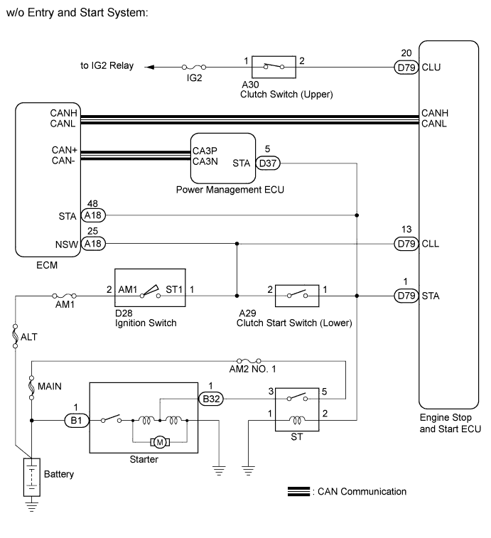
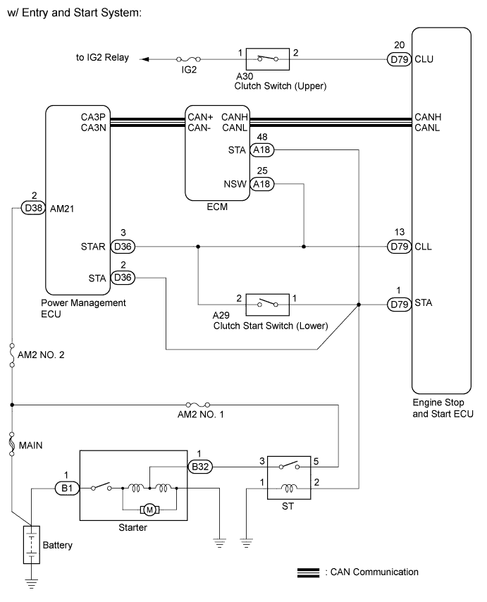
WIRING DIAGRAM
INSPECTION PROCEDURE
Note
-
If the engine stop and start ECU is being replaced, register the previously recorded number of starter operations into the new engine stop and start ECU Click here.
-
After the engine stop and start ECU is replaced or after an air conditioner kit is installed, clear the A/C information stored in the engine stop and start ECU Click here.
-
Inspect the fuses for circuits related to this system before performing the following inspection procedure.
PROCEDURE
-
READ VALUE USING INTELLIGENT TESTER (CLUTCH UPPER AND LOWER SIGNAL)
-
Connect the intelligent tester to the DLC3.
-
Turn the ignition switch to ON.
-
Turn the tester on.
-
Enter the following menus: Powertrain / Stop and Start / Data List / Clutch Upper SW and Clutch Lower SW.
-
Depress the clutch pedal and read the values displayed on the tester.
OK Item Clutch Pedal Condition Tester Display Clutch Upper SW Fully Depressed OFF Clutch Lower SW Fully Depressed ON Clutch Upper SW Fully Released ON Clutch Lower SW Fully Released OFF
NG 
INSPECT CLUTCH SWITCH (UPPER) Click here
OK 
USE SIMULATION METHOD TO CHECK Click here
-
-
INSPECT CLUTCH SWITCH (UPPER)
-
Inspect the clutch switch (upper) Click here.
NG 
REPLACE CLUTCH SWITCH (UPPER) Click here
OK 
-
-
INSPECT CLUTCH START SWITCH (LOWER)
-
Inspect the clutch start switch (lower) Click here.
NG
REPLACE CLUTCH START SWITCH (LOWER) Click here
OK
-
-
CHECK HARNESS AND CONNECTOR (ENGINE STOP AND START ECU - CLUTCH SWITCH UPPER)
-
Disconnect the engine stop and start ECU connector.
-
Disconnect the clutch switch (upper) connector.
-
Measure the resistance according to the value(s) in the table below.
Standard Resistance Tester Connection Condition Specified Condition D79-20 (CLU) - A30-2 Always Below 1 Ω D79-20 (CLU) or A30-2 - Body ground Always 10 kΩ or higher -
Turn the ignition switch to ON.
-
Measure the voltage according to the value(s) in the table below.
Standard Voltage Tester Connection Switch Condition Specified Condition D79-20 (CLU) - Body ground Ignition Switch ON Below 1 V -
Turn the ignition switch off.
-
Reconnect the engine stop and start ECU connector.
-
Reconnect the clutch switch (upper) connector.
NG
REPAIR OR REPLACE HARNESS OR CONNECTOR
OK
-
-
CHECK HARNESS AND CONNECTOR (ENGINE STOP AND START ECU - CLUTCH START SWITCH LOWER)
-
Disconnect the engine stop and start ECU connector.
-
Disconnect the clutch start switch (lower) connector.
-
Measure the resistance according to the value(s) in the table below.
Standard Resistance Tester Connection Condition Specified Condition D79-13 (CLL) - A29-2 Always Below 1 Ω D79-13 (CLL) - Body ground Always 10 kΩ or higher A29-2 - Body ground Always 10 kΩ or higher -
Reconnect the engine stop and start ECU connector and clutch start switch (lower) connector.
NG
REPAIR OR REPLACE HARNESS OR CONNECTOR
OK
REPLACE ENGINE STOP AND START ECU Click here
-