STOP AND START SYSTEM, Diagnostic DTC:P0500
| DTC Code | DTC Name |
|---|---|
| P0500 | Vehicle Speed Sensor "A" |
DESCRIPTION
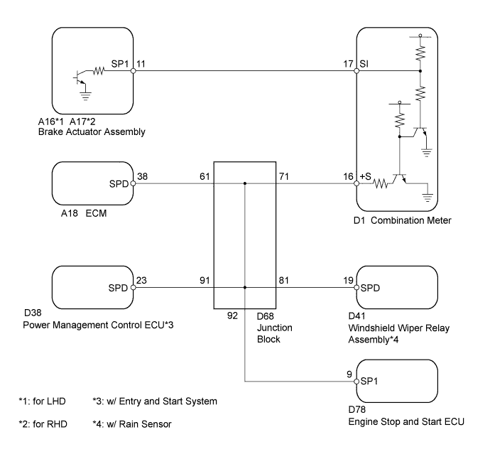
This description and the following Inspection Procedure are for DTC P0500 which is stored in the engine stop and start ECU. The speed sensors, which are mounted at each wheel, send wheel speed pulse signals to the skid control ECU. The skid control ECU converts the wheel speed pulse signals to a vehicle speed pulse signal and sends it to the combination meter assembly. The signal then goes to the ECM and engine stop and start ECU.
| DTC No. | DTC Detection Condition | Trouble Area |
|---|---|---|
| P0500 | All of the following conditions continue for 15 seconds or more (1 trip detection logic):
|
|
Tech Tips
DTCs for the Stop and Start system are not cleared even if the malfunction has been repaired. After repairing the malfunction, be sure to clear the DTCs Click here.
-
After troubleshooting, perform the following steps to recheck for DTCs.
Tech Tips
-
If the ECM learned values have been cleared by disconnecting the battery or for another reason, Stop and Start system control will be prohibited until ECM learning completes.
-
Allow the engine to idle for 3 minutes after the engine warms up and check that the engine speed is within 50 rpm of the target idle speed.
-
Clear the DTCs Click here.
-
Start the engine and drive the vehicle at 20 km/h (12.4 mph) or more for at least 30 seconds.
-
Check that no DTCs are output Click here.
-
-
Check if the Stop and Start system operates normally.
Tech Tips
If the battery terminal has been disconnected, the ECO OFF indicator will be illuminated. In this case, drive the vehicle for 15 to 40 minutes to turn off the indicator.
-
Warm up the engine.
-
Turn the air conditioning system off.
-
Drive the vehicle at 7 km/h (4.3 mph) or more.
-
Stop the vehicle. Move the shift lever to neutral and release the clutch pedal.
-
Check that the engine stops.
-
Depress the clutch pedal and check that the engine restarts.
-
WIRING DIAGRAM
INSPECTION PROCEDURE
Note
-
If the engine stop and start ECU is being replaced, register the previously recorded number of starter operations into the new engine stop and start ECU Click here.
-
After the engine stop and start ECU is replaced or after an air conditioner kit is installed, clear the A/C information stored in the engine stop and start ECU Click here.
-
Inspect the fuses for circuits related to this system before performing the following inspection procedure.
PROCEDURE
-
CHECK FOR DTC (BRAKE CONTROL SYSTEM)
-
Start the engine and drive the vehicle at 20 km/h (12.4 mph) or more for 5 minutes or more.
-
Connect the intelligent tester to the DLC3.
-
Check if any DTCs for the brake control system are output.
Tech Tips
Vehicle stability control system Click here.
Result Result Proceed to No DTCs for the brake control system are output A Brake control system DTC is output B
B 
GO TO VEHICLE STABILITY CONTROL SYSTEM Click here
A 
-
-
READ VALUE USING INTELLIGENT TESTER (VEHICLE SPEED)
-
Drive the vehicle and check whether the operation of the speedometer in the combination meter assembly is normal.
Tech Tips
-
The vehicle speed sensor is operating normally if the speedometer reading is normal.
-
If the speedometer does not operate, check it by following the procedure described for a speedometer malfunction Click here.
-
-
Connect the intelligent tester to the DLC3.
-
Start the engine.
-
Turn the tester on.
-
Enter the following menus: Powertrain / Stop and Start / Data List / Vehicle Spd 1(ABS/VSC), Vehicle Spd 2 (Spd Signal) and Vehicle Spd 3 (Spd Signal).
-
Perform a road test and check the Data List value and the speedometer reading.
OK The Data List values and the speedometer readings are almost the same. Tech Tips
The output of Vehicle Spd 2 may be delayed by a few seconds compared to Vehicle Spd 1. Check Vehicle Spd 1, 2 under stable conditions.
NG 
INSPECT COMBINATION METER (SPD SIGNAL WAVEFORM) Click here
OK 
USE SIMULATION METHOD TO CHECK Click here
-
-
INSPECT COMBINATION METER (SPD SIGNAL WAVEFORM)
-
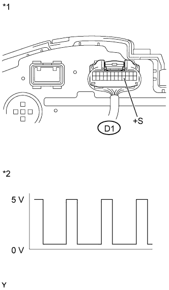
Text in Illustration *1 Component with harness connected:
(Combination Meter)
*2 Waveform (with turning wheel) Inspect the combination meter assembly using an oscilloscope.
-
Move the shift lever to neutral.
-
Jack up the vehicle.
-
Turn the ignition switch to ON.
-
Measure the voltage between the terminal of the combination meter assembly and body ground while any of the wheels is turned slowly (a speed equivalent to driving at about 3 km/h (1.8 mph)).
Standard Voltage Tester Connection Switch Condition Specified Condition D1-16 (+S) - Body ground
-
Ignition switch ON
-
Wheel turned slowly (at about 3 km/h (1.8 mph))
Voltage generated intermittently Tech Tips
The output voltage should fluctuate up and down, similar to the diagram, when the wheel is turned slowly (at about 3 km/h (1.8 mph)).
-
NG
GO TO METER / GAUGE SYSTEM (SPEED SIGNAL CIRCUIT) Click here
OK
-
-
CHECK HARNESS AND CONNECTOR (ENGINE STOP AND START ECU - COMBINATION METER ASSEMBLY)
-
Disconnect the engine stop and start ECU connector.
-
Disconnect the combination meter connector.
-
Measure the resistance according to the value(s) in the table below.
Standard Resistance Tester Connection Condition Specified Condition D78-9 (SP1) - D1-16 (+S) Always Below 1 Ω D78-9 (SP1) - Body ground Always 10 kΩ or higher D1-16 (+S) - Body ground Always 10 kΩ or higher -
Reconnect the engine stop and start ECU connector and combination meter connector.
NG
REPAIR OR REPLACE HARNESS OR CONNECTOR
OK
-
-
REPLACE ENGINE STOP AND START ECU
-
Replace the engine stop and start ECU Click here.
NEXT
-
-
CONFIRM DTC
-
Connect the intelligent tester to the DLC3.
-
Turn the ignition switch to ON.
-
Turn the tester on.
-
Drive the vehicle at 20 km/h (12.4 mph) or more.
-
Check that no DTCs are output Click here.
Result Result Proceed to DTC is not output A DTC is output B
B
REPLACE ECM Click here
A
END
-