STOP AND START SYSTEM DATA LIST / ACTIVE TEST
-
DATA LIST
Tech Tips
Using the intelligent tester to read the Data List allows the values or states of switches, sensors, actuators and other items to be read without removing any parts. This non-intrusive inspection can be very useful because intermittent conditions or signals may be discovered before parts or wiring is disturbed. Reading the Data List information early in troubleshooting is one way to save diagnostic time.
Note
In the table below, the values listed under "Normal Condition" are reference values. Do not depend solely on these reference values when deciding whether a part is faulty or not.
-
Warm up the engine.
-
Turn the ignition switch off.
-
Connect the intelligent tester to the DLC3.
-
Start the engine.
-
Turn the tester on.
-
Enter the following menus: Powertrain / Stop and Start / Data List.
-
Check the values by referring to the table below.
Tech Tips
The results of a test performed on an actual vehicle are shown in the "Result of Real-vehicle Check" column. Use these values as a reference.
*1: Regarding Battery Integrated CurrentStop and Start System Tester Display Measurement Item/Range Normal Condition Result of Real-vehicle Check Diagnostic Note Eco Warning ECO indicator light status:
0/1
0: ECO indicator light OFF or ON (not blinking) under system normal operation 0: ECO indicator light OFF 1: Any malfunction occurs in the system and the indicator light is blinking. Coolant Temp Engine coolant temperature:
Min.: 16°C (60.8°F), Max.: 127°C (260.6°F)
75 to 95°C (167 to 203°F): Idling after engine warmed up 85°C (185°F): Idling after engine warmed up This is sent from the ECM. Engine Spd (ECM) Engine speed signal from ECM through CAN communication:
Min.: 0 rpm, Max.: 12800 rpm
550 to 650 rpm: Idling after engine warmed up 600 rpm: Idling after engine warmed up This is sent from the ECM. Engine Spd (NE Signal) Engine speed signal (calculated from pulse signal):
Min.: 0 rpm, Max.: 25600 rpm
550 to 650 rpm: Idling after engine warmed up 600 rpm: Idling after engine warmed up The pulse signal is from NEO terminal of the ECM. Battery Voltage Battery voltage:
Min.: 0 V, Max.: 20 V
11 to 14 V: Idling 12.5 V: Idling stop condition - Battery Temp (Start) Battery temperature:
Min.: -40°C (-40°F), Max.: 100°C (212°F)
Close to actual temperature 55°C (131°F): Idling stop condition - A/C Outlet Temp A/C blower temperature:
Min.: -159°C (-254.2°F), Max.: 159°C (318.2°F)
Close to actual temperature 25°C (77°F): Idling stop condition Measured by duct air temperature sensor (cooler thermistor). D Courtesy Switch Signal Driver door courtesy switch signal:
ON/OFF
ON: Driver door open OFF: Driver side door closed - Hood Courtesy Switch Hood courtesy switch signal:
ON/OFF
ON: Engine hood closed ON: Engine hood closed - Neutral Switch Neutral position switch signal:
ON/OFF
ON: Shift lever in neutral ON: Shift lever in neutral - Clutch Upper SW Clutch switch (upper) signal:
ON/OFF
ON: Clutch pedal fully released ON: Clutch pedal released - Clutch Lower SW Clutch start switch (lower) signal:
ON/OFF
ON: Clutch pedal fully depressed OFF: Clutch pedal released - Starter Cranking operation status:
ON/OFF
ON: Cranking - - TC Terminal TC and CG terminals of DLC3:
ON/OFF
ON: TC and CG terminals of DLC3 are connected OFF: TC terminal not grounded - Alternator L Terminal Generator L terminal status:
ON/OFF
ON: No power being generated ON: Engine stopped due to Stop and Start system control
OFF: Engine running
- Oil Pressure Switch Oil pressure switch signal:
ON/OFF
ON: Engine stopped ON: Engine stopped
OFF: Engine running
- Cancel Switch Stop and start cancel switch signal:
ON/OFF
ON: Cancel switch pressed (ON) OFF: Cancel switch not pressed (OFF) - IG Switch Ignition switch signal:
ON/OFF
ON: Ignition switch ON ON: Ignition switch ON - Idle Engine idling status:
ON/OFF
ON: Throttle closed ON: Throttle closed This is sent from the ECM. Starter Input Signal Starter input signal:
ON/OFF
ON: Starter relay being supplied with power OFF: Ignition switch ON Starter drive signal at engine restart Engine Start (IG SW) Manual engine starting method:
ON/OFF
ON: Engine started by ignition switch operation OFF: Ignition switch ON Starter operated due to driver key operation Stop Light SW (ECM) Stop light switch signal:
ON/OFF
ON: Stop lights ON OFF: Brake pedal released This signal is sent from the ECM. Indicat. Light ECO OFF ECO OFF indicator light:
ON/OFF
ON: Light ON (vehicle stopped, and any of Stop and Start system control prohibit condition have been met) ON: Light ON while the engine idling (not stopped due to Stop and Start system control) This indicator light is illuminated while Stop and Start system control is prohibited (the vehicle is stopped). Buzzer Buzzer status:
ON/OFF
ON: Buzzer ON OFF: Buzzer does not sound Refer to System Description Click here.
Indicat. Light Oil Oil pressure warning light status:
ON/OFF
ON: Engine stopped for any reason other than Stop and Start system control OFF: Engine stopped due to Stop and Start system control - Indicat. Light Eco ECO warning light status:
ON/OFF
ON: ECO warning light ON or blinking ON: Engine stopped due to Stop and Start system control - Starter Request Starter operation request signal:
ON/OFF
ON: Starter operated by engine stop and start ECU ON: Requested engine restart - Starter Operation # Number of starter operations (count record):
Min.: 0, Max.: 1048575
- 5182: Reference - Vehicle Spd 1 (ABS/VSC) Vehicle speed signal from skid control ECU (through CAN communication):
Min.: 0 km/h (0 mph), Max.: 327.67 km/h (203.6 mph)
0 km/h (0 mph): Vehicle stopped 12 km/h (7.4 mph): Idling stop condition - Vehicle Spd 2 (Spd Signal) Vehicle speed signal (calculated from pulse signal):
Min.: 0 km/h (0 mph), Max.: 512 km/h (318.1 mph)
0 km/h (0 mph): Vehicle stopped 12 km/h (7.4 mph): Idling stop condition The pulse signal from combination meter Vehicle Spd 3 (Spd Signal) Vehicle speed signal for diagnosis (calculated from pulse signal):
Min.: 0 km/h (0 mph), Max.: 255 km/h (158.4 mph)
0 km/h (0 mph): Vehicle stopped 12 km/h (7.4 mph): Idling stop condition The pulse signal from combination meter Battery Current Battery current:
Min.: -125 A, Max.: 124.99 A
Battery discharge current -6.38 A: Engine stopped due to Stop and Start system control - Brake Boost Pressure Brake booster pressure (absolute pressure):
Min.: 0 kPa (0 mmHg), Max.: 112 kPa (840 mmHg)
Approx. 100 kPa (750 mmHg): Ignition switch ON, brake pedal depressed several times (differs according to atmospheric pressure) 30 kPa (225 mmHg): Idling stop condition - Brake Negative Pressure Brake booster vacuum (negative pressure):
Min.: 0 kPa (0 mmHg), Max.: 640 kPa (4800 mmHg)
0 kPa (0 mmHg): Ignition switch ON, brake pedal depressed several times 73.22 kPa (549 mmHg): Idling stop condition
(Brake Negative Pressure = Estimated atmospheric pressure - Brake Boost Pressure)
This item cannot be checked if an error occurs in communication with the ECM. Ambient Temp Sensor Ambient temperature:
Min.: 0°C (32°F), Max.: 80°C (176°F)
Close to ambient air temperature 25.0°C (77°F): Reference - Stop&Start of Eng State Stop and Start system control status:
IG / Run / Stopreq / Stop / Restart
-
IG: Before engine started
-
Run: Engine running
-
Stopreq: Engine stop requested
-
Stop: Engine stopped
-
Restart: Engine restarted
Stop: Engine stopped due to Stop and Start system control - Integrated Current
*1
Battery integrated current calculated from the battery current sensor signal:
Min.: -268434.45 A-sec, Max.: 268435.45 A-sec
Differs according to the vehicle condition (charge/discharge conditions) 1349.36 A-sec: Engine stopped due to Stop and Start system control Refer to "Regarding Battery Integrated Current" below for details. Cranking Time Engine cranking time (in present trip):
Min.: 0 ms, Max.: 134215 ms
0.3 to 3.5 seconds: Accumulated starter on time due to Stop and Start system control 391.16 ms: Engine stopped due to Stop and Start system control - Min Voltage (Cranking) Minimum battery voltage while engine cranking (in present trip):
Min.: 0 V, Max.: 327.67 V
6 to 10 V 10.23 V Lowest battery voltage measured in a 5 second period after the starter starts operating. State of BBC Backup boost converter status (diagnostic result):
Cycle Err / Overvol / Overload / Normal / Low Vol / Duty Err
Normal: Backup boost converter operating normally Normal: Engine stopped due to Stop and Start system control
-
Duty Err:
-
Inappropriate DDON duty value is detected.
-
Cycle Err:
-
DDON duty cycle deviates beyond the allowable range.
-
Low Vol:
-
A decrease in the voltage of the control IC power source within the backup boost converter is detected when ignition switch is ON.
-
Overload:
-
Overcurrent is detected such as an audio excessive volume.
-
Overvol:
-
When the ignition switch is ON:
-
Overvoltage is detected at the control IC power source within the backup boost converter.
-
Overheating is detected at the control IC power source within the backup boost converter.
-
When boosting:
-
Error is detected in the feedback circuit in the backup boost converter.
-
Too high or low output voltage.
Refer to DTC P323B.
BBC Check Result Backup boost converter over-load status (fuse function status):
Normal/Abnormal
Normal: Backup boost converter operating normally Normal: Engine stopped due to Stop and Start system control Excessive amperage load when the backup boost converter is boosting the voltage during engine start. Atmosphere Pressure Atmospheric pressure (calculated value):
Min.: 0 kPa (0 mmHg), Max.: 255 kPa (1913 mmHg)
Approx. 100 kPa (750 mmHg): Ignition switch ON (close to actual atmospheric pressure) 103 kPa (775 mmHg): Engine stopped due to Stop and Start system control ECM calculated value EPS Load Electric power steering current:
Min.: -327.68 A, Max.: 327.67 A
Approx. 0 A: EPS assist is not activated 0.02 A: Engine stopped due to Stop and Start system control - Accelerator Position Accelerator pedal opening:
Min.: 0 deg, Max.: 56.5 deg
0 deg: Accelerator pedal fully released 0.0 deg: Accelerator pedal fully released ECM calculated value Engine OFF Request Engine stop request:
ON/OFF
ON: Stop and Start system control activated ON: Engine stopped due to Stop and Start system control ON is shown when fuel cut is performed due to Stop and Start system control, engine start is not requested, engine is stopped, or starter is forced to operate. Wrong Operation (Start) Wrong operation for engine start:
ON/OFF
ON: Shift lever operated without depressing clutch pedal while the engine is stopped due to Stop and Start system control OFF: Engine stopped due to Stop and Start system control - Vehicle Speed Zero Vehicle speed status:
ON/OFF
ON: Vehicle stopped ON: Engine stopped due to Stop and Start system control - Engine Reverse Rev. Engine reverse revolution status:
ON/OFF
ON: Engine turning in reverse direction OFF: Engine stopped due to Stop and Start system control This is sent from the ECM. Stop and Start Cancel Stop and start control prohibition status by cancel switch:
ON/OFF
ON: Stop and Start system control prohibited by stop and start cancel switch OFF: Engine stopped due to Stop and Start system control - Starter Check Starter circuit malfunction detection monitor status:
Compl/Incompl
Compl: Before vehicle stopped after starter drive circuit check completes Compl: During start request condition
(No DTC output)
Compl is displayed only when starter drive circuit check completes normally. The starter drive circuit check is performed from when the vehicle speed becomes low (10 km/h (6.5 mph) or less) until the vehicle stops. Blower Switch A/C blower switch status:
ON/OFF
ON: Blower fan operating OFF: Blower switch off - Clutch Upper SW History Clutch switch (upper) status record:
ON/OFF
ON: Clutch switch (upper) OFF record is detected (remains ON until next Stop and Start system control or the shift lever is moved to any drive range) OFF: Engine stopped due to Stop and Start system control Checked each drive cycle Neutral Switch History Neutral position switch status record:
ON/OFF
ON: Neutral position switch OFF record is detected (remains ON until next Stop and Start system control) OFF: Engine stopped due to Stop and Start system control Checked each drive cycle N/Clutch Lower SW Abnoml Neutral position switch and clutch start switch (lower) malfunction detection status:
ON/OFF
ON: Neutral position switch or clutch start switch (lower) malfunction OFF: Engine stopped due to Stop and Start system control - N/Clutch Upper SW Abnoml Neutral position switch and clutch switch (upper) malfunction detection status:
ON/OFF
ON: Neutral position switch or clutch switch (lower) malfunction OFF: Engine stopped due to Stop and Start system control - Permit Idling Stop Engine stop standby:
ON/OFF
ON: Stop and Start system control is available OFF: Engine stopped due to Stop and Start system control
Before vehicle stopped after on condition is met
- Running History Vehicle driving record:
ON/OFF
ON: The history of the vehicle was driven at 2 km/h (1.2 mph) or more (with no DTC stored) ON: Before vehicle stopped after on condition is met ON remains displayed until next engine restart. Auto A/C Whether vehicle is equipped with auto or manual air conditioning:
Without/With
Without: Not equipped with auto or manual air conditioning
With: Equipped with auto or manual air conditioning
With: with auto or manual air conditioning system A/C information needs to be registered after ECU replacement Click here.
A/C Request Engine start request from A/C system:
ON/OFF
ON: A/C needs engine running to maintain required blow-off port temperature etc. OFF: Engine stopped due to Stop and Start system control Measured by duct air temperature sensor (cooler thermistor) Neutral Switch Neutral condition for stop and start control:
ON/OFF
ON: Transmission shift lever in neutral ON: Engine stopped due to Stop and Start system control - Idling Engine idling condition for stop and start control:
ON/OFF
ON: Engine running (engine speed is 1000 rpm or less), and throttle valve fully closed ON: Engine is idling - Vehicle Speed Zero Vehicle speed condition for stop and start control:
ON/OFF
ON: Vehicle stopped ON: Engine stopped due to Stop and Start system control ON is shown after the vehicle remains stopped for a certain period. Stop&Start Precondition Preconditions for stop and start control:
ON/OFF
ON: Preconditions for Stop and Start system control have been met ON: Before idling stop control For details on the preconditions, refer to System Description Click here.
ECM 1 Precondition for stop and start control (engine system condition):
ON/OFF
ON: Engine control conditions for Stop and Start system control have been met and no malfunctions in SFI system ON: Engine stopped due to Stop and Start system control - ECM 2 Precondition for stop and start control (engine system condition):
ON/OFF
ON: Engine control conditions for Stop and Start system control have been met ON: Engine stopped due to Stop and Start system control This is sent from the ECM through CAN communication. ECM 3 Precondition for stop and start control (engine system condition):
ON/OFF
ON: Engine control permits fuel cut, or Active Test (forced permission) is performed ON: Engine stopped due to Stop and Start system control - IG Switch Precondition for stop and start control (ignition switch condition):
ON/OFF
ON: Ignition switch ON for 5 seconds or more ON: Engine stopped due to Stop and Start system control
(ignition switch ON)
- Detect DTC Precondition for stop and start control (DTC detection):
ON/OFF
ON: DTCs detected OFF: Engine stopped due to Stop and Start system control - Brake Negative Pressure Precondition for stop and start control (brake booster condition):
ON/OFF
ON: Brake vacuum is more than about 45 kPa (338 mmHg) for 1 second ON: Engine stopped due to Stop and Start system control - Rest Time (Stop and Start) Precondition for stop and start control (engine running time):
ON/OFF
ON: More than 5 seconds pass after engine restarted due to Stop and Start system control OFF: Engine stopped due to Stop and Start system control - Driver side Door Close Precondition for stop and start control (driver door condition):
ON/OFF
ON: Driver door closed ON: Engine stopped due to Stop and Start system control - Engine Hood Close Precondition for stop and start control (engine hood condition):
ON/OFF
ON: Engine hood closed ON: Engine stopped due to Stop and Start system control - Air Conditioning ECU Precondition for stop and start control (A/C condition):
ON/OFF
ON: No request to start engine from A/C, or Active Test (forced permission) is performed ON: Engine stopped due to Stop and Start system control - After Running Precondition for stop and start control (vehicle drive condition after first ignition switch turned ON):
ON/OFF
ON: After driving at a speed of more than 7 km/h (4.3 mph) ON: Engine stopped due to Stop and Start system control ON is shown until the ignition switch turned to OFF. Neutral Switch History Precondition for stop and start control (neutral position switch status record):
ON/OFF
ON: Neutral position switch OFF record is detected (remains ON until next Stop and Start system control) OFF: Engine stopped due to Stop and Start system control Checked each drive cycle Clutch Upper SW History Precondition for stop and start control (clutch switch (upper) status record):
ON/OFF
ON: Clutch switch (upper) OFF record is detected (remains ON until next Stop and Start system control) OFF: Engine stopped due to Stop and Start system control Checked each drive cycle Battery Precondition for stop and start control (battery condition):
ON/OFF
ON: Stop and Start system control is permitted due to battery condition, or Active Test (forced permission) is performed - - Battery Voltage Cond 1 Precondition for stop and start control (battery voltage):
ON/OFF
ON: Battery temperature 0°C (32°F) or less and minimum battery voltage 7.2 V or higher when engine running OFF: Engine stopped due to Stop and Start system control If two or more from Battery Voltage Cond 1, 2, 3, and 4 are ON, Stop and Start system control is permitted. Battery Voltage Cond 2 Precondition for stop and start control (battery voltage):
ON/OFF
ON: Battery temperature higher than 0°C (32°F) and minimum battery voltage 7.2 V or higher when engine running ON: Engine stopped due to Stop and Start system control If two or more from Battery Voltage Cond 1, 2, 3, and 4 are ON, Stop and Start system control is permitted. Battery Voltage Cond 3 Precondition for stop and start control (battery voltage):
ON/OFF
ON: Battery temperature 0°C (32°F) or less and minimum battery voltage 7.2 V or higher when engine starting OFF: Engine stopped due to Stop and Start system control If two or more from Battery Voltage Cond 1, 2, 3, and 4 are ON, Stop and Start system control is permitted. Battery Voltage Cond 4 Precondition for stop and start control (battery voltage):
ON/OFF
ON: Battery temperature higher than 0°C (32°F) and minimum voltage 7.2 V or higher when engine starting ON: Engine stopped due to Stop and Start system control If two or more from Battery Voltage Cond 1, 2, 3, and 4 are ON, Stop and Start system control is permitted. Battery Current Precondition for stop and start control (battery current):
ON/OFF
ON: Battery discharge current of 50 A or less ON: Engine stopped due to Stop and Start system control Power management ECU calculated value Battery Integrated Current
*1
Precondition for stop and start control (battery integrated current):
ON/OFF
ON: Accumulated battery current (electrical discharge current value) below a certain level
(2246 A-sec)
ON: Engine stopped due to Stop and Start system control The status depends on the value of "Integrated Current", and ON/OFF threshold differs according to the battery temperature.
Refer to "Regarding Battery Integrated Current" below for details.
Power Management Precondition for stop and start control (power source system condition):
ON/OFF
ON: Power management system normal ON: Engine stopped due to Stop and Start system control If any malfunction occurs in the power management system, the engine may not restart due to Stop and Start system control. Therefore, Stop and Start system control is prohibited. Jump Start Precondition for stop and start control (engine hood open condition when engine starts):
ON/OFF
ON: Engine started with the engine hood open and the ignition switch to the START position OFF: Engine stopped due to Stop and Start system control If "Jump Start" is detected, Stop and Start system control is prohibited for that trip. Manual Start Precondition for stop and start control (engine start condition):
ON/OFF
ON: Engine started due to any operation other than key operation or Stop and Start system control (manual start) OFF: Engine stopped due to Stop and Start system control If manual engine start is detected, Stop and Start system control is prohibited for that trip.
-
Conditions for Manual Start:
-
Clutch start switch (lower) OFF or vehicle speed signal (pulse signal) input
-
Neutral position switch OFF
-
Starter signal OFF
Alternator Gen Rate Precondition for stop and start control (generator condition):
ON/OFF
ON: Generator is not generating a large amount of power ON: Engine stopped due to Stop and Start system control If the generator is generating a large amount of power, Stop and Start system control is prohibited. After Starting Precondition for stop and start control (engine running time condition):
ON/OFF
ON: A maximum of 4 minutes have elapsed after engine restarted OFF: Before engine restarts (changes to ON 5 seconds after engine restarts) - Input Vehicle Speed Vehicle speed condition for engine start request:
ON/OFF
ON: Vehicle speed signal input while engine stopped due to Stop and Start system control OFF: Engine stopped due to Stop and Start system control (vehicle stopped) If a vehicle speed signal is detected during idle stop, the engine is restarted. Brk Negative Pressure Low Brake booster vacuum condition for engine start request:
ON/OFF
ON: Brake booster vacuum insufficient while engine stopped due to Stop and Start system control -
-
OFF is usually displayed.
-
ON is displayed when the engine is started due to decreased brake booster vacuum caused by depressing the brake pedal several times.
Battery Condition Battery voltage condition for engine start request:
ON/OFF
ON: Battery voltage low while engine stopped due to Stop and Start system control OFF: Engine stopped due to Stop and Start system control - IG Switch Engine start request from ignition switch operation:
ON/OFF
ON: Ignition switch turned to START during Stop and Start system control OFF: Engine stopped due to Stop and Start system control - ECM Engine start request from ECM:
ON/OFF
ON: Engine stop and start ECU operates starter relay when engine start request signal received from ECM via CAN OFF: Engine stopped due to Stop and Start system control - Air Conditioning A/C condition for engine start request:
ON/OFF
ON: A/C needs engine running to maintain required temperature while engine stopped due to Stop and Start system control OFF: Engine stopped due to Stop and Start system control - EPS Power steering condition for engine start request:
ON/OFF
ON: Power steering is operated while engine stopped due to Stop and Start system control OFF: Engine stopped due to Stop and Start system control - Power Management Power management system condition for engine start request:
ON/OFF
ON: Malfunction occurs in power management system or backup boost converter during Stop and Start system control OFF: Engine stopped due to Stop and Start system control - Detect DTC DTC detection status for engine start request:
ON/OFF
ON: Any DTCs detected during Stop and Start system control OFF: Engine stopped due to Stop and Start system control
(No DTC detected)
- Clutch Pedal Clutch pedal status for engine start request:
ON/OFF
ON: Clutch pedal depressed without wrong shift operation OFF: Engine stopped due to Stop and Start system control
(Clutch pedal released)
- Engine Hood Open Engine hood switch condition:
ON/OFF
ON: Engine hood open (with clutch start switch (lower) signal ON and neutral position switch signal ON) while engine stopped due to Stop and Start system control OFF: Engine hood is closed - Battery Battery status for engine start request:
ON/OFF
ON: Engine start requested due to low battery voltage while engine stopped due to Stop and Start system control OFF: Engine stopped due to Stop and Start system control - Battery Voltage Low 1 Low battery voltage:
ON/OFF
ON: Battery voltage drops when the engine is stopped due to Stop and Start system control OFF: Engine stopped due to Stop and Start system control - Battery Voltage Low 2 Low battery voltage:
ON/OFF
ON: Urgent engine start request due to low battery voltage while engine stopped due to Stop and Start system control OFF: Engine stopped due to Stop and Start system control - Before Running Before driving condition and after ignition switch is turned to ON:
ON/OFF
OFF: Before driving at more than 7 km/h (4.3 mph) after ignition switch ON OFF: Engine stopped due to Stop and Start system control - Steering Action Power steering condition for stop and start control:
ON/OFF
OFF: Usually OFF: Usually - ABS Running ABS condition for stop and start control:
ON/OFF
ON: ABS operating OFF: ABS not operating - BBC Abnoml Backup boost converter malfunction detection status:
ON/OFF
OFF: System normal OFF: No DTC output Refer to DTC P323B. IG SW Abnoml Ignition switch circuit malfunction detection status:
ON/OFF
OFF: System normal OFF: No DTC output Refer to DTC P2531. Battery Abnoml Battery malfunction detection status:
ON/OFF
OFF: System normal OFF: No DTC output Refer to DTC P0562. Starter Circuit Malfunction Starter circuit malfunction detection status for fail-safe function:
ON/OFF
OFF: System normal OFF: No DTC output Refer to DTC P1644. Spd Sensor Malfunction 1 Vehicle speed signal malfunction:
ON/OFF
OFF: System normal OFF: No DTC output Vehicle speed signal is interrupted (0 km/h (0 mph) is detected). NE Sensor Circuit Open 2 Engine speed signal malfunction detection status for fail-safe function:
ON/OFF
OFF: System normal OFF: No DTC output ON: No pulse signal from ECM while the engine is cranking (Stop and Start system control will be prohibited). NE Sensor Circuit Open 3 Engine speed signal malfunction detection status for fail-safe function:
ON/OFF
OFF: System normal OFF: No DTC output ON: Difference between the NE signal (pulse signal from ECM) and the engine speed information (through CAN communication) is more than a threshold.
Refer to DTC P0335.
Brk Boost Sen Malfunction Brake booster pressure signal malfunction detection status for fail-safe function:
ON/OFF
OFF: System normal OFF: No DTC output Refer to DTC P1540, P1541. Spd Sensor Malfunction 2 Vehicle speed signal malfunction detection status for fail-safe function:
ON/OFF
OFF: System normal OFF: No DTC output ON: Difference between the vehicle speed signal (pulse signal from combination meter) and vehicle speed information (through CAN communication) is more than a threshold.
Refer to DTC P0500.
Starter Circuit Open STA signal circuit malfunction detection status for fail-safe function:
ON/OFF
OFF: System normal OFF: No DTC output Refer to DTC P1545. Starter Count Error Starter operation counter status for fail-safe function:
ON/OFF
OFF: Number of starter operations below specified value OFF: No DTC output Refer to DTC P1545. # Codes Number of detected DTCs:
Min.: 0, Max.: 127
Number of DTC output 0: No DTC output - In the Stop and Start system, the engine stop and start ECU switches the system control mode (Stop and Start system control permitted/prohibited) based on the battery condition (charge/discharge condition) to protect the battery and to ensure stable engine restarting performance.
The battery charge-discharge condition is determined from the integrated current value calculated from the battery current sensor signal. The integrated current value is obtained by multiplying the current (Ampere) detected from the battery current sensor by the time (seconds), and it is expressed in a unit A-sec.
Example: Integrated current of -3110 A-sec corresponds to a load where current of 10 A flows out from the battery for 311 seconds.
Using the Data List function of the intelligent tester, the integrated current value can be read by checking the Data List item "Integrated Current". The item "Battery Integrated Current" shows the permission status of Stop and Start system control and is judged from the "Integrated Current" value.
Negative integrated current represents battery discharge, and positive represents battery charge. In other words, the "Integrated Current" value of the Data List item will decrease from the present value when the battery is discharged, and the value will increase when the battery is charged.
The engine stop and start ECU determines the power charge based on the integrated current value, and it prohibits Stop and Start system control if the value is below the threshold, because the battery might not be able to start the engine. The threshold varies according to the battery temperature and battery charge condition.
Furthermore, the integrated current value is recorded inside the engine stop and start ECU memory even if the ignition switch is off, and when the ignition switch is next turned to ON, the value is calculated from the value recorded when the ignition switch was turned off.
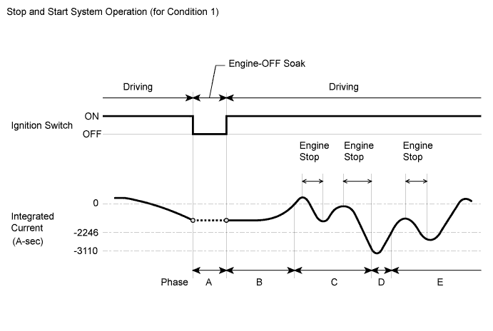
Integrated Current Condition 1:When a low battery temperature condition is not detected (the battery temperature is 11°C (51.8°F) or more) and battery charge condition is good:
-
Phase A:
When the ignition switch is turned off, the integrated current value is recorded in the ECU memory. The value is carried over to the next trip.
-
Phase B:
After engine start by ignition switch operation, Stop and Start system control is prohibited until the integrated current reaches 0 A-sec once. (The battery is being charged during this phase.)
-
Phase C:
Stop and Start system control is permitted until the integrated current decreases to -3110 A-sec.
-
Phase D:
After the integrated current value decreases below -3110 A-sec, Stop and Start system control is prohibited until the value increases to -2246 A-sec or more again. (The battery is being charged during this phase.)
-
Phase E:
Stop and Start system control is permitted. After this, system control is permitted until the integrated current decreases below -3110 A-sec.
Stop and Start System Operation (for Condition 1)
When a low battery temperature condition is detected (the battery temperature is less than 10°C (50°F)):
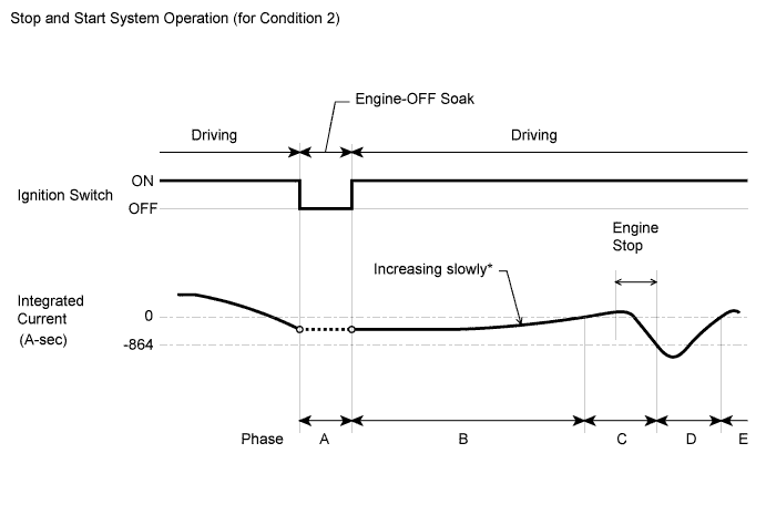
*: The integrated current increases slowly due to low battery charge acceptance at low temperature.
-
Phase A:
When the ignition switch is turned off, the integrated current value is recorded in the ECU memory. The value is carried over to the next trip.
-
Phase B:
After engine start by ignition switch operation, Stop and Start system control is prohibited until the integrated current reaches 0 A-sec once. (The battery is being charged during this phase.)
-
Phase C:
Stop and Start system control is permitted until the integrated current decreases to -864 A-sec.
-
Phase D:
After the integrated current value decreases below -864 A-sec, Stop and Start system control is prohibited until the value increase to 0 A-sec or more again. (The battery is being charged during this phase.)
-
Phase E:
Stop and Start system control is permitted. If the battery temperature becomes 11°C (51.8°F) or higher and the battery charge condition meets a predetermined condition, Stop and Start system operation switches to Integrated Current Condition 1 above.
Stop and Start System Operation (for Condition 2)
Tech Tips
-
The low battery temperature condition is detected when the battery temperature is less than 10°C (50°F). When the battery temperature becomes 11°C (51.8°F) or more, the low battery temperature condition is cleared.
-
Performance (internal resistance) of lead-acid batteries used in typical vehicles changes according to the battery temperature. The internal resistance of the battery tends to be higher when the battery temperature is low. Thus, the Stop and Start system switches the threshold for determining the power charge according to the battery temperature when performing stop and start control.
-
If the battery is deteriorated, the internal resistance has also increased and the stop and start rate becomes lower. (The total of idling time while the vehicle is stopped increases.)
-
When troubleshooting, if the malfunction cannot be identified, the battery might be deteriorated.
-
-
ACTIVE TEST
Tech Tips
Using the intelligent tester to perform Active Tests allows relays, actuators and other items to be operated without removing any parts. This non-intrusive functional inspection can be very useful because intermittent operation may be discovered before parts or wiring is disturbed. Performing Active Tests early in troubleshooting is one way to save diagnostic time. Data List information can be displayed while performing Active Tests.
-
Connect the intelligent tester to the DLC3.
-
Start the engine.
-
Turn the tester on.
-
Enter the following menus: Powertrain / Stop and Start / Active Test.
-
Perform the Active Test by referring to the table below.
Stop and Start System Tester Display Test Part Control Range Diagnostic Note Buzzer Buzzer activation ON/OFF - Starter Starter activation ON/OFF Refer to DTC P1545 if the test is unavailable. Permit Cond (A/C) A/C ON/OFF - Permit Cond (Battery) Battery ON/OFF - Permit Cond (Engine) Engine ON/OFF - Start Cond (Hood Crtsy) Engine hood ON/OFF - Tech Tips
Even if Stop and Start system control is prohibited due to the condition of any of the systems listed above, performing the Active Tests allows Stop and Start system control to be performed.
-