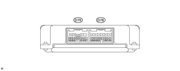
STOP AND START SYSTEM TERMINALS OF ECU
-
ENGINE STOP AND START ECU
Tech Tips
The standard voltage and resistance between each pair of ECU terminals are shown in the table below.
The appropriate conditions for checking each pair of terminals are also indicated.
The check results should be compared with the standard voltage, listed in the "Specified Condition" column.
The illustration above can be used to identify the ECU terminal locations.
Terminal No.
(Symbol)
Wiring Color Terminal Description Condition Specified Condition D79-1 (STA) - D78-6 (E1) L - W-B Starter operation signal Cranking 6 V or higher D79-4 (NE) - D78-6 (E1) P - W-B Engine speed signal from ECM Idling after engine warmed up Pulse generation
(see waveform 1)
D79-5 (BATT) - D78-6 (E1) GR - W-B Battery voltage (for engine stop and start ECU memory) Always 11 to 14 V D79-6 (+B) - D78-6 (E1) G - W-B Power source for engine stop and start ECU Ignition switch ON, engine stopped 10 to 14 V Ignition switch off 0 to 0.5 V D79-9 (BNT1) - D78-6 (E1) BE - W-B Engine hood courtesy switch signal Ignition switch ON, engine stopped, engine hood closed 0 to 1.5 V Ignition switch ON, engine stopped, engine hood open 10 to 14 V D79-10 (TMN) - D78-6 (E1) W - W-B Neutral position switch signal Ignition switch ON, shift lever in neutral 0 to 1.5 V Ignition switch ON, shift lever in any position other than neutral 10 to 14 V D79-11 (PB) - D79-24 (E2) Y - B Brake booster pressure sensor signal Ignition switch ON, absolute pressure of 40 kPa (300 mmHg) applied to sensor 1.6 to 2.0 V Ignition switch ON, absolute pressure of 60 kPa (450 mmHg) applied to sensor 2.2 to 2.6 V Ignition switch ON, atmospheric pressure applied to vacuum sensor 3.4 to 3.8 V D79-12 (RL) - D78-6 (E1) R - W-B Generator signal Idling after engine warmed up 10 to 14 V Ignition switch ON, engine stopped 0 to 1.5 V D79-13 (CLL) - D78-6 (E1) V - W-B Clutch start switch (lower) signal Clutch pedal released 10 to 14 V Clutch pedal fully depressed 0 to 1.5 V D79-18 (DDON) - D78-6 (E1) V - W-B Backup boost converter signal Engine running Pulse generation
(see waveform 2)
D79-19 (VC) - D78-6 (E1) BR - W-B Vacuum sensor power supply Ignition switch ON, engine stopped 4.5 to 5.5 V D79-20 (CLU) - D78-6 (E1) G - W-B Clutch switch (upper) signal Clutch pedal released 10 to 14 V Clutch pedal depressed 0 to 1.5 V D79-22 (MOPS) - D78-6 (E1) LG - W-B Oil pressure switch signal Ignition switch ON, engine stopped 0 to 1.5 V Idling after engine warmed up 10 to 14 V D79-24 (E2) - Body ground B - Body ground Sensor circuit ground wire Always Below 1 Ω D78-1 (EC) - Body ground BR - Body ground Body ground wire Always Below 1 Ω D78-6 (E1) - Body ground W-B - Body ground Body ground wire Always Below 1 Ω D78-7 (ECLP) - D78-6 (E1) BE - W-B Stop and start cancel switch (illumination) System disabled using stop and start cancel switch after ignition switch turned to ON (indicator on) 0 to 2.5 V System not disabled using stop and start cancel switch after ignition switch turned to ON (indicator off) 10 to 14 V D78-8 (ECAN) - D78-6 (E1) R - W-B Stop and start cancel switch Ignition switch ON, stop and start cancel switch on 0 to 1.5 V Ignition switch ON, stop and start cancel switch off 10 to 14 V D78-9 (SP1) - D78-6 (E1) W - W-B Vehicle speed signal Ignition switch ON, drive wheel rotated slowly Pulse generation
(see waveform 3)
D78-10 (TFAL) - D79-24 (E2) V - B A/C cooler thermistor signal Ignition switch ON, A/C on with set temperature of 10 to 30°C (50 to 86°F) 2.4 to 2.9 V D78-16 (CANH) - D78-6 (E1) BE - W-B CAN communication circuit Ignition switch ON Pulse generation
(see waveform 4)
D78-17 (CANL) - D78-6 (E1) W - W-B CAN communication circuit Ignition switch ON Pulse generation
(see waveform 5)
D78-19 (IGSW) - D78-6 (E1) SB - W-B Ignition switch signal Ignition switch ON, engine stopped 10 to 14 V Ignition switch off 0 to 0.5 V D78-22 (SBL) - D78-6 (E1) G - W-B Blower switch signal Ignition switch ON, blower switch on 0 to 1.5 V Ignition switch ON, blower switch off 10 to 14 V D78-26 (OIL) - D78-6 (E1) LG - W-B Engine oil pressure warning light signal Ignition switch ON, engine stopped (engine oil pressure warning light on) 5 to 6 V Ignition switch ON, engine idling (engine oil pressure warning light off) 10 to 14 V
-
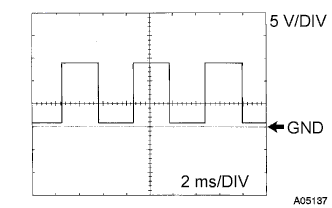
Waveform 1
Engine Speed Signal Item Content Tester connection D79-4 (NE) - D78-6 (E1) Tool setting 5 V/DIV, 2 ms/DIV Vehicle condition Idling after engine warmed up Tech Tips
The wavelength becomes shorter as the engine speed increases.
-
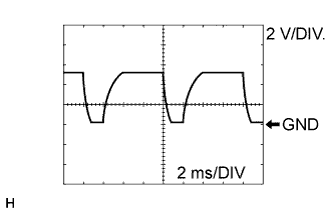
Waveform 2
Backup Boost Converter Signal Item Content Tester connection D79-18 (DDON) - D78-6 (E1) Tool setting 2 V/DIV, 2 ms/DIV Vehicle condition Engine running Tech Tips
The wavelength becomes shorter as the engine speed increases.
-
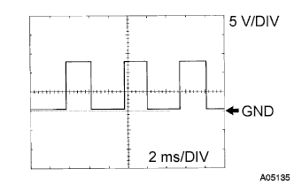
Waveform 3
Vehicle Speed Signal Item Content Tester connection D78-9 (SP1) - D78-6 (E1) Tool setting 5 V/DIV, 2 ms/DIV Vehicle condition Ignition switch ON, drive wheel rotated slowly Tech Tips
The wavelength becomes shorter as the vehicle speed increases.
-
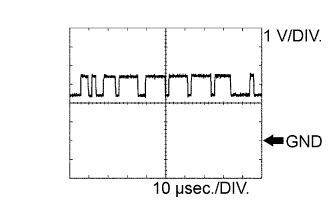
Waveform 4
CAN Communication Signal (Reference) Item Content Tester connection D78-16 (CANH) - D78-6 (E1) Tool setting 1 V/DIV., 10 μsec./DIV. Vehicle condition Ignition switch ON Tech Tips
The waveform varies depending on the CAN communication signal.
-
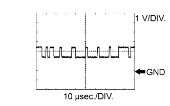
Waveform 5
CAN Communication Signal (Reference) Item Content Tester connection D78-17 (CANL) - D78-6 (E1) Tool setting 1 V/DIV., 10 μsec./DIV. Vehicle condition Ignition switch ON Tech Tips
The waveform varies depending on the CAN communication signal.
-