OIL PUMP REMOVAL

-
REMOVE ENGINE ASSEMBLY WITH TRANSAXLE
-
Remove the engine assembly with transaxle Click here.
-
-
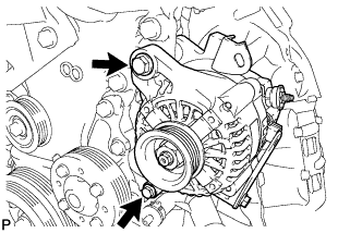
REMOVE GENERATOR ASSEMBLY
-
Remove the 2 bolts and the generator.
-
-
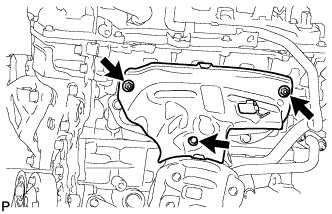
REMOVE NO. 1 EXHAUST MANIFOLD HEAT INSULATOR
-
Remove the bolt, 2 nuts and the No. 1 exhaust manifold heat insulator.
-
-
REMOVE MANIFOLD STAY

-
Remove the bolt, nut and the manifold stay.
-
-
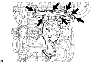
REMOVE EXHAUST MANIFOLD CONVERTER SUB-ASSEMBLY
-
Remove the 3 bolts, 4 nuts and the exhaust manifold converter.
-
Remove the exhaust manifold to head gasket and inlet EGR gasket from the cylinder head.
-
-
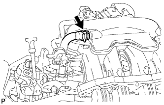
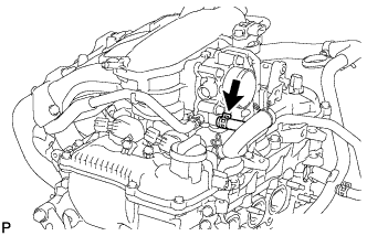
DISCONNECT VENTILATION HOSE
-
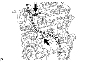
Loosen the clip and disconnect the ventilation hose from the intake manifold.
-
-
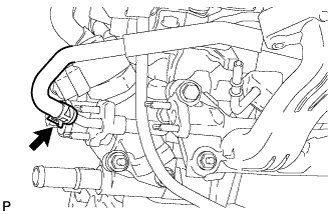
DISCONNECT NO. 2 WATER BY-PASS HOSE
-
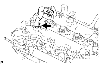
Loosen the clip and disconnect the No. 2 water by-pass hose from the throttle body.
-
-
DISCONNECT NO. 4 WATER BY-PASS HOSE
-
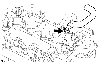
Loosen the clip and disconnect the No. 4 water by-pass hose from the EGR valve.
-
-
REMOVE INTAKE MANIFOLD STAY

-
Remove the 2 bolts and the intake manifold stay.
-
-
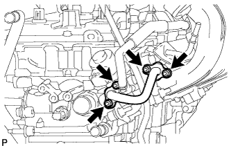
REMOVE EGR PIPE CONNECTOR
-
Remove the 4 nuts and the EGR pipe connector.
-
Remove the 2 EGR pipe gaskets from the intake manifold and EGR valve.
-
-
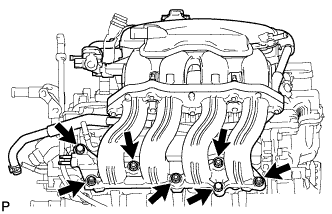
REMOVE INTAKE MANIFOLD ASSEMBLY
-
Remove the 5 bolts, 2 nuts and the intake manifold.
-
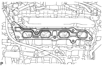
Remove the intake manifold to head gasket from the cylinder head.
-
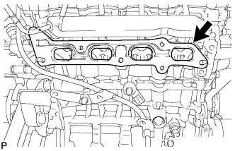
Remove the EGR delivery chamber from the cylinder head.
-
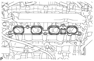
Remove the No. 2 intake manifold to head gasket from the cylinder head.
-
-
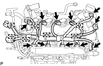
REMOVE NO. 4 ENGINE WIRE
-
Disconnect the 2 camshaft timing oil control valve connectors.
-
Disconnect the 4 ignition coil connectors.
-
Disconnect the 4 fuel injector connectors.
-
Remove the ground bolt.
-
Disengage the 7 clamps and remove the No. 4 engine wire.
-
-
REMOVE ENGINE OIL LEVEL DIPSTICK
-
REMOVE ENGINE OIL LEVEL DIPSTICK GUIDE
-
Remove the 2 bolts and the engine oil level dipstick guide.
-
Remove the O-ring from the oil level dipstick guide.
-
-
REMOVE NO. 1 IGNITION COIL
-
Remove the 4 bolts and remove the 4 No. 1 ignition coils.
-
-
REMOVE VENTILATION HOSE
-
Remove the ventilation hose from the cylinder head cover.
-
-
REMOVE NO. 2 VENTILATION HOSE
-
Remove the No. 2 ventilation hose from the cylinder head cover.
-
-
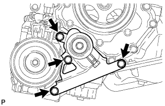
REMOVE NO. 1 WATER BY-PASS PIPE
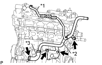
Text in Illustration *1 No. 2 Water By-Pass Hose *2 No. 1 Water By-Pass Pipe *3 Water By-Pass Hose
-
Disengage the No. 2 water by-pass hose from the 3 clamps.
-
Remove the 3 bolts.
-
Disconnect the water by-pass hose and remove the No. 1 water by-pass pipe.
-
-
REMOVE NO. 2 IDLE PULLEY ASSEMBLY (w/ Air Conditioning System)
-
Remove the 4 bolts and the No. 2 idle pulley assembly with bracket.
-
-
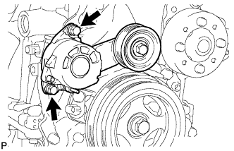
REMOVE V-RIBBED BELT TENSIONER ASSEMBLY
-
Remove the 2 bolts and the V-ribbed belt tensioner.
-
-
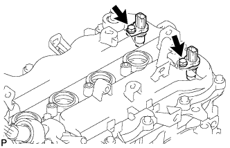
REMOVE NO. 1 CRANKSHAFT POSITION SENSOR
-
Remove the 2 bolts and the 2 No. 1 crankshaft position sensors.
-
-
REMOVE CYLINDER HEAD COVER SUB-ASSEMBLY
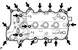
Text in Illustration *1 Seal Washer
-
Remove the 18 bolts, 2 seal washers and the cylinder head cover.
Note
Be careful not to drop any of the gaskets into the engine when removing the cylinder head cover because the gaskets may stick to the cylinder head cover.
-
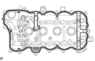
Remove the cylinder head cover gasket.
-
-
REMOVE CAMSHAFT BEARING CAP OIL HOLE GASKET
-
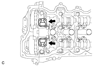
Remove the 2 camshaft bearing cap oil hole gaskets from the camshaft bearing cap.
-
-
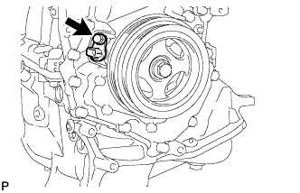
REMOVE CRANK POSITION SENSOR
-
Remove the bolt and the crankshaft position sensor.
-
-
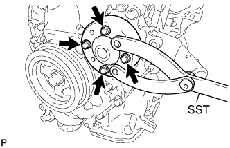
REMOVE WATER PUMP PULLEY
-
Using SST, remove the 4 bolts and water pump pulley.
- SST
- 09960-10010 ( 09962-01000, 09963-00600 )
-
-
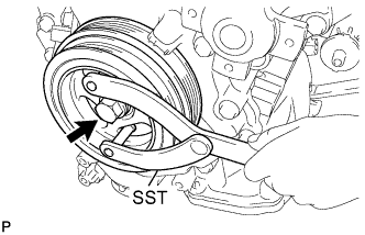
REMOVE CRANKSHAFT PULLEY ASSEMBLY
-
Using SST, remove the crankshaft pulley bolt.
- SST
- 09960-10010 ( 09962-01000, 09963-01000 )
-
Remove the crankshaft pulley from the crankshaft.
-
-
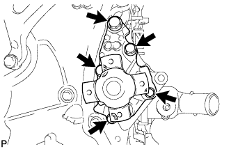
REMOVE TIMING CHAIN COVER SUB-ASSEMBLY
-
Remove the 5 bolts and the water pump, water pump gasket from the timing chain cover.
-
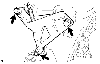
Remove the 3 bolts and the engine mounting bracket.
-
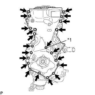
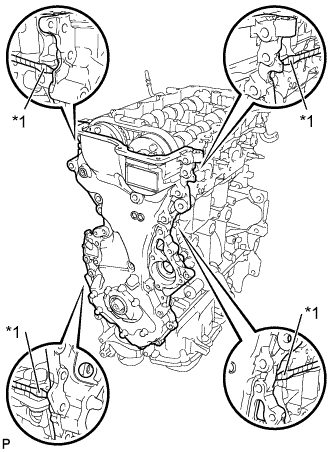
Text in Illustration *1 Seal Washer Remove the 21 bolts and seal washer.
-
Text in Illustration *1 Protective Tape Using a screwdriver with its tip wrapped with protective tape, remove the timing chain cover by prying between the timing chain cover and cylinder head or cylinder block.
Note
Be careful not to damage the contact surfaces of the timing chain cover, cylinder block, and cylinder head.
Tech Tips
Tape the screwdriver tip before use.
-
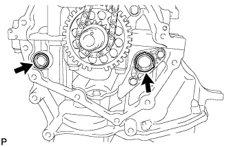
Remove the 2 O-rings.
-
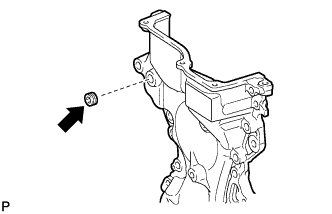
Using an 8 mm socket hexagon wrench, remove the plug.
-
-
REMOVE TIMING CHAIN COVER OIL SEAL
-
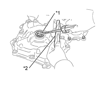
Text in Illustration *1 Protective Tape *2 Wooden Block Using a screwdriver with its tip wrapped in protective tape, remove the timing chain cover oil seal.
Note
Do not damage the surface of the oil seal press fit hole.
-
-
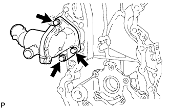
REMOVE WATER INLET
-
Remove the 3 bolts and the water inlet.
-
-
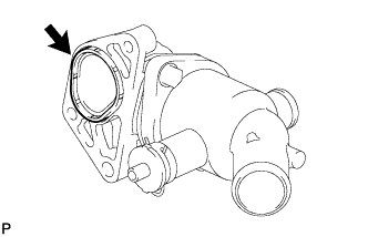
REMOVE NO. 2 WATER INLET HOUSING GASKET
-
Remove the No. 2 water inlet housing gasket from the water inlet.
-