OIL PUMP INSTALLATION

-
INSTALL TIMING CHAIN OR BELT COVER OIL SEAL
-
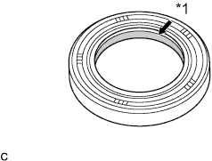
Apply engine oil to the lip of a new oil seal.
Text in Illustration *1 Apply Engine Oil. -
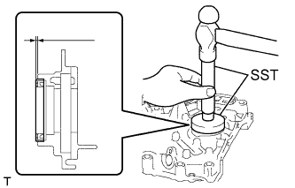
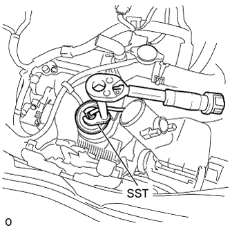
Using SST, tap the oil seal straight in.
- SST
- 09950-60010 ( 09951-00500, 09952-06010 )
- 09950-70010 ( 09951-07200 )
Correct oil seal position Protrusion from chain cover edge 0.5 mm (0.020 in.) or less Installation depth from chain cover edge 1.0 mm (0.039 in.) or less
-
-
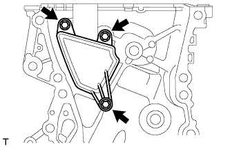
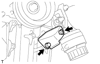
INSTALL VENTILATION CASE SUB-ASSEMBLY
-
Install the ventilation case sub-assembly with the 3 bolts.
- Torque:
- 10 N*m { 102 kgf*cm, 7 ft.*lbf }
-
-
INSTALL STUD BOLT
-
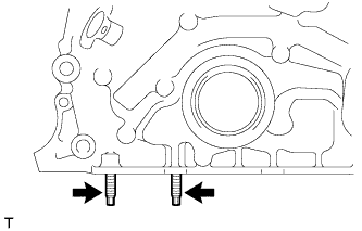
Install the 2 stud bolts.
-
-
INSTALL TIMING CHAIN OR BELT COVER SUB-ASSEMBLY
-
Remove any oil packing (FIPG) material and be careful not to drop any oil on the contact surfaces of the timing chain cover sub-assembly, cylinder head, and cylinder block.
-
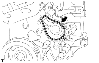
Apply seal packing as shown in the illustration.
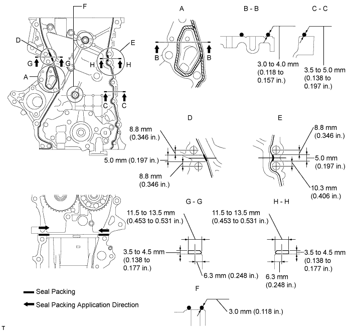
Seal packing Toyota Genuine Seal Packing Black, Three Bond 1207B or equivalent. Note
-
Install the timing chain cover sub-assembly within 3 minutes and tighten the bolts within 15 minutes after applying seal packing.
-
Do not add engine oil for at least 2 hours after installation.
-
Do not start the engine for at least 2 hours after installation.
-
-
Temporarily install the timing chain cover sub-assembly with the 12 bolts.
Bolt Length Item Length Bolt A 80 mm (3.15 in.) Bolt B 40 mm (1.57 in.) Bolt C 45 mm (1.77 in.) Bolt D 70 mm (2.78 in.) Bolt E 45 mm (1.77 in.) -
Install the new gasket to the timing chain cover sub-assembly.
-
Temporarily install the oil filter bracket with the 2 bolts.
Bolt Length Item Length Bolt A 20 mm (0.79 in.) Bolt B 119 mm (4.69 in.) -
Install the new gasket to the timing chain cover sub-assembly.
-
Temporarily install the water pump assembly with 5 bolts.
Bolt Length Item Length Bolt A 55 mm (2.17 in.) Bolt B 20 mm (0.79 in.) -
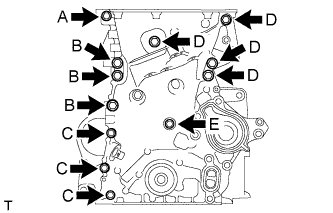
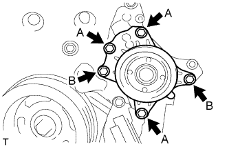
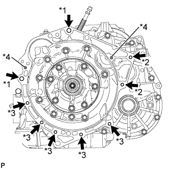
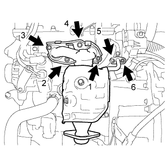
Fully tighten the timing chain cover sub-assembly with the 19 bolts as shown in the illustration.

- Torque:
- 24 N*m { 245 kgf*cm, 18 ft.*lbf, (Bolt A, C, E, F, G) }
- 40 N*m { 408 kgf*cm, 30 ft.*lbf, (Bolt B, D) }
- 10 N*m { 102 kgf*cm, 7 ft.*lbf, (Bolt H) }
Note
-
Install the chain cover within 3 minutes and tighten the bolts within 15 minutes after applying seal packing.
-
Do not add engine oil for at least 2 hours after installation.
-
Do not start the engine for at least 2 hours after installation.
Bolt Length Item Length Bolt A 80 mm (3.15 in.) Bolt B 40 mm (1.57 in.) Bolt C 45 mm (1.77 in.) Bolt D 70 mm (2.78 in.) Bolt E 55 mm (2.17 in.) Bolt F 20 mm (0.79 in.) Bolt G 119 mm (4.69 in.) Bolt H 45 mm (1.77 in.) -
Remove excess seal packing.
-
Using an E8 "TORX" socket, install the 2 stud bolts.
-
-
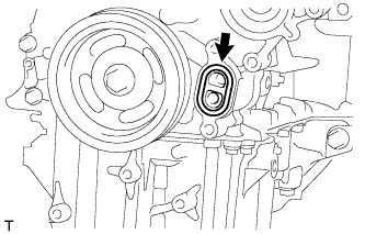
INSTALL TIMING GEAR COVER TIGHT PLUG
-
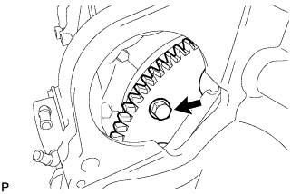
Remove the hexagon wrench from the timing chain tensioner sub-assembly.
Tech Tips
Before removing, slightly turn the hexagonal portion of the camshaft assembly counterclockwise to leave some slack on the chain of the timing chain tensioner sub-assembly side.
-
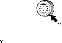
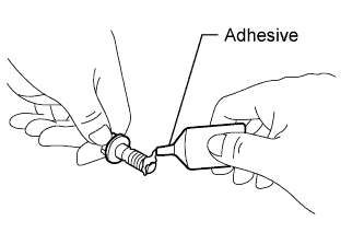
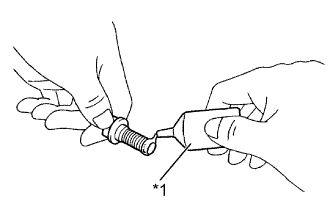
Text in Illustration *1 Adhesive Clean the plug and the bolt holes of the timing chain cover and apply adhesive to the threads of the plug.
Adhesive Toyota Genuine Adhesive 1324, Three Bond 1324 or equivalent -
Using an 8 mm socket hexagon wrench, install the timing gear tight plug.
- Torque:
- 10 N*m { 102 kgf*cm, 7 ft.*lbf }
-
-
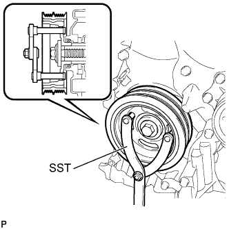
INSTALL CRANKSHAFT PULLEY
-
Align the pulley set key with the key groove of the pulley.
-
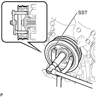
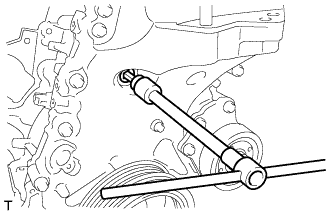
Using SST, hold the pulley in place and tighten the bolt.
- SST
- 09960-10010 ( 09962-01000, 09963-01000 )
- Torque:
- 180 N*m { 1835 kgf*cm, 133 ft.*lbf }
-
-
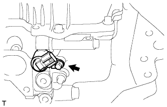
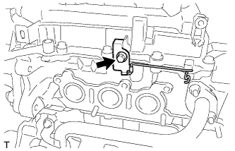
INSTALL CAMSHAFT TIMING OIL CONTROL VALVE ASSEMBLY
-
Apply a light coat of engine oil to the O-ring.
-
Install the camshaft timing oil control valve assembly with the bolt.
- Torque:
- 10 N*m { 102 kgf*cm, 7 ft.*lbf }
-
Connect the camshaft timing oil control valve assembly connector.
-
-
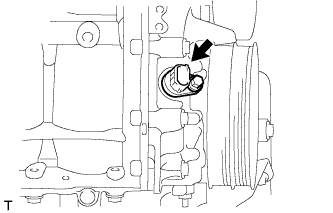
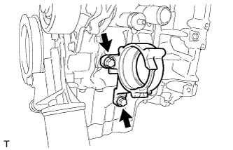
INSTALL CRANKSHAFT POSITION SENSOR
-
Apply a light coat of engine oil to the O-ring.
-
Install the crankshaft position sensor with the bolt.
- Torque:
- 8.0 N*m { 82 kgf*cm, 71 in.*lbf }
-
Connect the crankshaft position sensor connector.
-
-
INSTALL OIL STRAINER SUB-ASSEMBLY
-
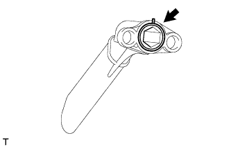
Install a new gasket to the oil strainer sub-assembly.
-
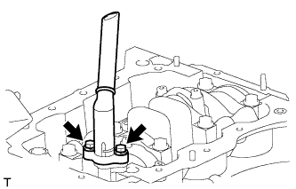
Install the oil strainer sub-assembly with the 2 bolts.
- Torque:
- 8.5 N*m { 87 kgf*cm, 76 in.*lbf }
-
-
INSTALL OIL PAN SUB-ASSEMBLY
-
Remove any grease from the installation surfaces of the cylinder block sub-assembly and oil pan sub-assembly.
-
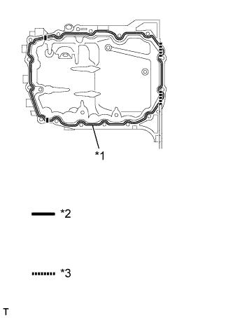
Apply seal packing to the oil pan sub-assembly and install it onto the cylinder block assembly.
Text in Illustration *1 Seal Packing *2 Contact surface between timing chain cover and cylinder block *3 Contact surface between oil seal retainer and cylinder block Seal packing Toyota Genuine Seal Packing Black, Three Bond 1207B or equivalent. Note
-
Start and finish applying the seal packing on the seal surface with the cylinder block sub-assembly.
-
Apply seal packing to the contact surfaces between the timing chain cover and cylinder block, and between the oil seal retainer and cylinder block.
-
Install the oil pan sub-assembly within 3 minutes and tighten the bolts within 15 minutes of applying the seal packing.
-
-
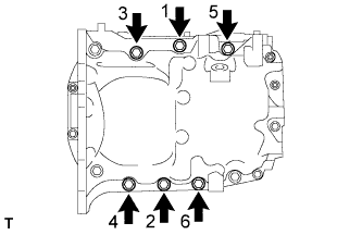
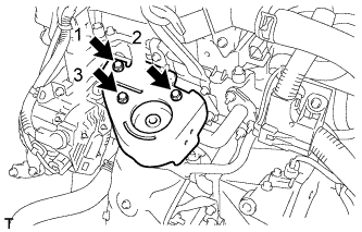
Tighten the specified 6 bolts in the order shown in the illustration.
- Torque:
- 24 N*m { 245 kgf*cm, 18 ft.*lbf }
-
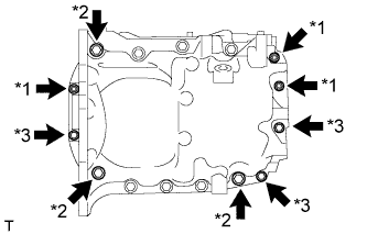
Text in Illustration *1 Nut *2 Bolt A *3 Bolt B Tighten the 6 bolts and 3 nuts.
- Torque:
- 10 N*m { 102 kgf*cm, 7 ft.*lbf, (Nut and Bolt B) }
- 24 N*m { 245 kgf*cm, 18 ft.*lbf, (Bolt A) }
-
-
INSTALL OIL FILTER BRACKET STAY
-
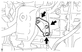
Install the oil filter bracket stay with the 2 bolts.
- Torque:
- 24 N*m { 245 kgf*cm, 18 ft.*lbf }
-
-
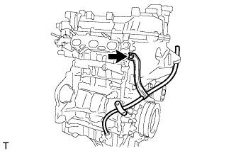
INSTALL NO. 1 WATER BY-PASS PIPE
-
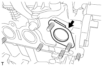
Install a new gasket to the cylinder head.
-
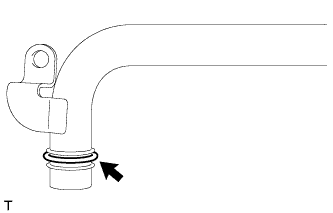
Install a new gasket to the No. 1 water by-pass pipe.
-
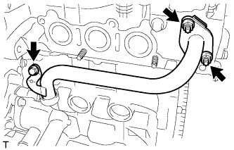
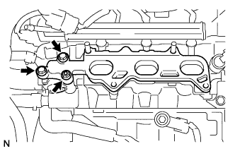
Temporarily tighten the bolt and install the 2 nuts.
- Torque:
- 24 N*m { 245 kgf*cm, 18 ft.*lbf }
-
Fully tighten the bolt.
- Torque:
- 24 N*m { 245 kgf*cm, 18 ft.*lbf }
-
-
INSTALL CYLINDER HEAD COVER SUB-ASSEMBLY
-
Remove any oil packing (FIPG) material and be careful not to drop any oil on the contact surfaces of the timing chain cover sub-assembly, cylinder head, and cylinder block.
-
Apply seal packing as shown in the illustration.
Seal packing Toyota Genuine Seal Packing Black, Three Bond 1207B or equivalent. Note
-
Install the timing chain cover sub-assembly within 3 minutes and tighten the bolts within 15 minutes after applying seal packing.
-
Do not add engine oil for at least 2 hours after installation.
-
Do not start the engine for at least 2 hours after installation.
-
-
Temporarily install the timing chain cover sub-assembly with the 12 bolts.
Bolt Length Item Length Bolt A 80 mm (3.15 in.) Bolt B 40 mm (1.57 in.) Bolt C 45 mm (1.77 in.) Bolt D 70 mm (2.78 in.) Bolt E 45 mm (1.77 in.) -
Install the new gasket to the timing chain cover sub-assembly.
-
Temporarily install the oil filter bracket with the 2 bolts.
Bolt Length Item Length Bolt A 20 mm (0.79 in.) Bolt B 119 mm (4.69 in.) -
Install the new gasket to the timing chain cover sub-assembly.
-
Temporarily install the water pump assembly with 5 bolts.
Bolt Length Item Length Bolt A 55 mm (2.17 in.) Bolt B 20 mm (0.79 in.) -
Fully tighten the timing chain cover sub-assembly with the 19 bolts as shown in the illustration.
- Torque:
- 24 N*m { 245 kgf*cm, 18 ft.*lbf, (Bolt A, C, E, F, G) }
- 40 N*m { 408 kgf*cm, 30 ft.*lbf, (Bolt B, D) }
- 10 N*m { 102 kgf*cm, 7 ft.*lbf, (Bolt H) }
Note
-
Install the chain cover within 3 minutes and tighten the bolts within 15 minutes after applying seal packing.
-
Do not add engine oil for at least 2 hours after installation.
-
Do not start the engine for at least 2 hours after installation.
Bolt Length Item Length Bolt A 80 mm (3.15 in.) Bolt B 40 mm (1.57 in.) Bolt C 45 mm (1.77 in.) Bolt D 70 mm (2.78 in.) Bolt E 55 mm (2.17 in.) Bolt F 20 mm (0.79 in.) Bolt G 119 mm (4.69 in.) Bolt H 45 mm (1.77 in.) -
Remove excess seal packing.
-
Using an E8 "TORX" socket, install the 2 stud bolts.
-
-
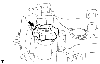
INSTALL OIL FILLER CAP SUB-ASSEMBLY
-
Install the oil filler cap sub-assembly.
-
-
INSTALL DRIVE SHAFT BEARING BRACKET
-
Install the drive shaft bearing bracket with the 2 bolts.
- Torque:
- 64 N*m { 650 kgf*cm, 47 ft.*lbf }
-
-
INSTALL WIRE HARNESS CLAMP BRACKET
-
Install the wiring harness clamp bracket with the bolt.
- Torque:
- 12 N*m { 122 kgf*cm, 9 ft.*lbf }
-
-
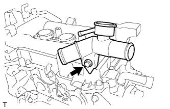
INSTALL WATER FILLER ASSEMBLY
-
Install the water filler assembly with the bolt.
- Torque:
- 13 N*m { 127 kgf*cm, 10 ft.*lbf }
-
-
INSTALL OIL LEVEL DIPSTICK GUIDE SUB-ASSEMBLY
-
Install the new O-ring to the oil level dipstick guide sub-assembly.
-
Install the oil level dipstick guide sub-assembly with the bolt.
- Torque:
- 10 N*m { 102 kgf*cm, 7 ft.*lbf }
-
-
INSTALL OIL LEVEL DIPSTICK SUB-ASSEMBLY
-
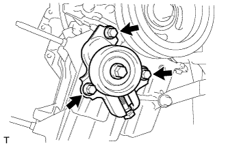
INSTALL IDLER PULLEY
-
Install the idler pulley with the 3 bolts.
- Torque:
- 25 N*m { 255 kgf*cm, 18 ft.*lbf }
-
-
INSTALL NO. 2 RADIATOR HOSE
-
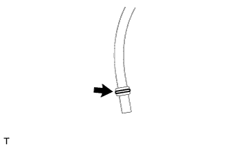
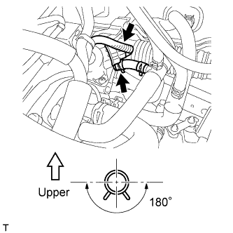
Install the No. 2 radiator hose with the clip.
Tech Tips
Install the clip as shown in the illustration.
-
-
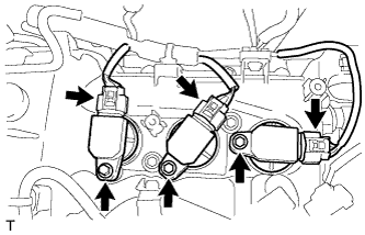
INSTALL NO. 1 IGNITION COIL
-
Install the 3 No. 1 ignition coils with the 3 bolts.
- Torque:
- 9.0 N*m { 91 kgf*cm, 80 in.*lbf }
-
Connect the 3 No. 1 ignition coil connectors.
-
-
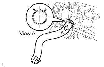
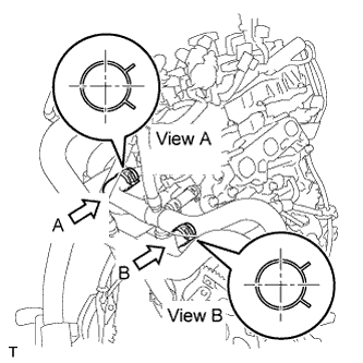
INSTALL NO. 1 RADIATOR HOSE
-
Install the No. 1 radiator hose with the 2 clips.
Tech Tips
Install the clip as shown in the illustration.
-
-
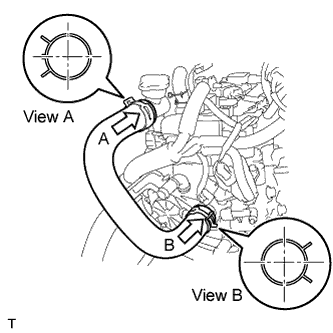
INSTALL WATER BY-PASS HOSE ASSEMBLY
-
Install the water by-pass hose assembly with the 2 clips.
Tech Tips
Install the clips as shown in the illustration.
-
-
INSTALL EGR VALVE ASSEMBLY
-
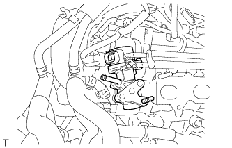
Install a new gasket to the cylinder head.
-
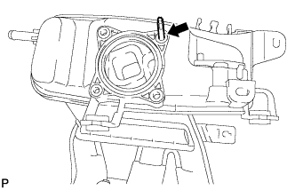
Insert the EGR valve into the stud bolt, rotate the EGR valve to avoid contact with the delivery pipe, and temporarily install the EGR valve.
-
Connect the water by-pass hose.
-
Connect the EGR valve connector.
-
-
INSTALL NO. 1 INTAKE MANIFOLD INSULATOR
-
Temporarily install the intake manifold insulator with a new gasket, the 2 bolts and the nut.
-
-
INSTALL INTAKE MANIFOLD
-
Install the stud bolt on the intake manifold.
-
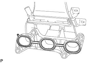
Install a new gasket on the intake manifold.
-
Temporarily install the intake manifold with the 2 bolts and 2 nuts.
-
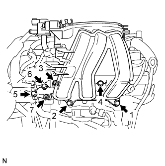
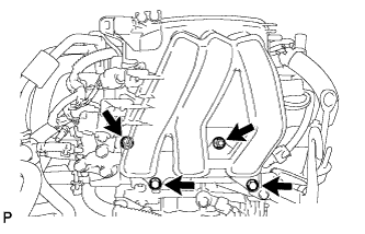
Tighten the 4 bolts and 3 nuts in the sequence shown in the illustration.
- Torque:
- 30 N*m { 306 kgf*cm, 22 ft.*lbf }
-
Connect the union to check valve hose with the hose clamp.
-
Connect the vacuum hose.
-
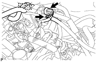
Connect the ventilation hose with the hose clamp.
-
Tighten the 2 bolts.
- Torque:
- 9.0 N*m { 92 kgf*cm, 80 in.*lbf }
-
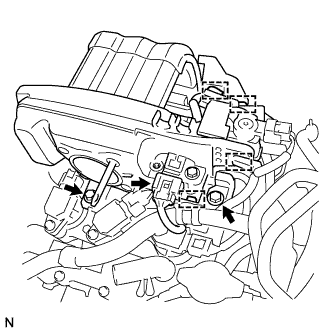
Engage the 4 wire harness clamps and install the wire harness to the intake manifold.
-
Connect the vacuum sensor connector.
-
Install the 2 water by-pass hoses on the intake manifold.
-
Connect the fuel vapor feed hose with the hose clamp.
-
Connect the vacuum switching valve connector
-
-
INSTALL THROTTLE WITH MOTOR BODY ASSEMBLY
-
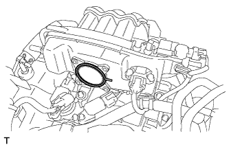
Install the new gasket onto the intake manifold.
-
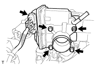
Install the throttle with motor body assembly with the 3 bolts and nut.
- Torque:
- 10 N*m { 102 kgf*cm, 7 ft.*lbf }
-
Connect the throttle with motor body assembly connector.
-
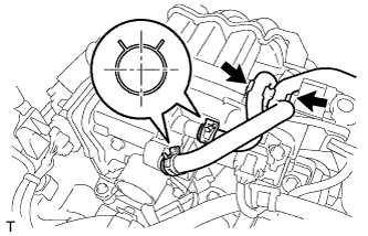
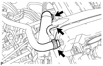
Connect the 2 water by-pass hoses with the 2 clips.
Tech Tips
Install the clips as shown in the illustration.
-
Install the 2 water by-pass hoses to the hose clamp.
-
-
INSTALL GENERATOR ASSEMBLY
-
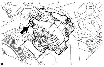
Temporarily install the generator assembly with the bolt.
-
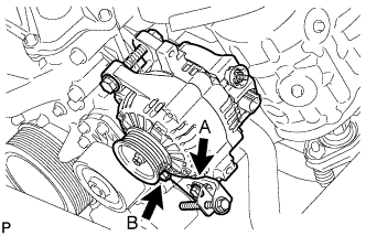
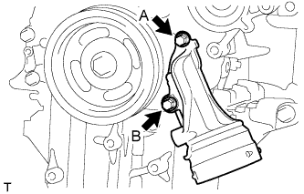
Temporarily install the fan belt adjusting bar with bolt A and bolt B.
-
Tighten bolt B with the generator assembly near the cylinder block.
- Torque:
- 21 N*m { 214 kgf*cm, 16 ft.*lbf }
-
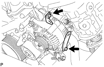
Install the 2 brackets with the 2 bolts.
- Torque:
- 8.0 N*m { 82 kgf*cm, 71 in.*lbf }
-
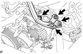
Connect the connector and wire harness clamps.
-
Install the terminal B with the nut.
- Torque:
- 9.8 N*m { 100 kgf*cm, 87 in.*lbf }
-
Install the terminal cap.
-
-
INSTALL DRIVE PLATE AND RING GEAR SUB-ASSEMBLY (for CVT)
-
Using SST, hold the crankshaft.
- SST
- 09960-10010 ( 09962-01000, 09963-01000 )
-
Clean the 6 bolts and the 6 bolt holes.
-
Apply adhesive to 2 or 3 threads of the bolt end.
Adhesive Toyota Genuine Adhesive 1324, Three Bond 1324 or equivalent. -
Text in Illustration *1 Front Drive Spacer *2 Drive Plate *3 Rear Drive Plate Spacer Install the front drive plate spacer.
Tech Tips
The front spacer is reversible.
-
Install the drive plate and rear drive plate spacer onto the crankshaft.
-
In several steps, uniformly install and tighten the 6 bolts in the sequence shown in the illustration.
- Torque:
- 78 N*m { 800 kgf*cm, 58 ft.*lbf }
-
-
INSTALL CONTINUOUSLY VARIABLE TRANSAXLE ASSEMBLY (for CVT)
-
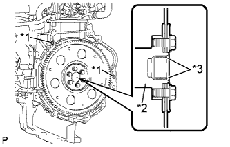
Text in Illustration *1 Knock Pin Confirm that 2 knock pins are on the transaxle contact surface of the engine cylinder block before transaxle installation.
-
Apply clutch spline grease to the round of the crankshaft contact surface (*3) with the torque converter centerpiece.
Text in Illustration *2 Crankshaft Clutch spline grease Toyota Genuine Clutch Spline Grease or equivalent Maximum spread Approximately 1 g (0.353 oz) -
- Torque:
- *1
- 64 N*m { 653 kgf*cm, 47 ft.*lbf }
- *2
- 37 N*m { 377 kgf*cm, 27 ft.*lbf }
- *3
- 39 N*m { 398 kgf*cm, 29 ft.*lbf }
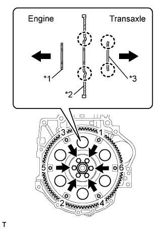
Maintain the engine and CVT in a horizontal position, align the knock pins and holes*4, and tighten the 9 bolts shown the illustration.
- Torque:
- *1
- 64 N*m { 653 kgf*cm, 47 ft.*lbf }
- *2
- 37 N*m { 377 kgf*cm, 27 ft.*lbf }
- *3
- 39 N*m { 398 kgf*cm, 29 ft.*lbf }
Note
-
Confirm that there are 2 knock pins on the fitting surface of the engine block before installing the CVT.
-
Do not twist or apply excessive force to the CVT.
-
Check that the torque converter rotates smoothly after installation of the CVT.
Tech Tips
-
*1: 45 mm (1.77 in.)
-
*2: 45 mm (1.77 in.)
-
*3: 35 mm (1.38 in.)
Bolt length
-
-
INSTALL DRIVE PLATE AND TORQUE CONVERTER CLUTCH SETTING BOLT (for CVT)
-
Clean and degrease the 6 drive plate and torque converter setting bolts.
-
Apply adhesive to 2 or 3 threads on the ends of the 6 torque converter set bolts.
Text in Illustration *1 Adhesive Adhesive Toyota Genuine Adhesive 1324, Three Bond 1324 or equivalent -
Use SST to hold the crankshaft pulley in place.
- SST
- 09960-10010 ( 09962-01000, 09963-01000 )
-
Install the 6 torque converter set bolts.
- Torque:
- 28 N*m { 286 kgf*cm, 21 ft.*lbf }
Tech Tips
Tighten the black-colored bolt first, and then tighten the 5 silver-colored bolts.
-
-
INSTALL STARTER ASSEMBLY
-
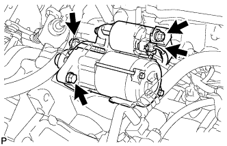
Install the starter assembly with the 2 bolts.
- Torque:
- 37 N*m { 377 kgf*cm, 27 ft.*lbf }
-
Connect the connector.
-
Connect the cable to terminal 30 with the nut.
- Torque:
- 9.8 N*m { 100 kgf*cm, 87 in.*lbf }
-
Close the terminal cap.
-
-
INSTALL FLYWHEEL SUB-ASSEMBLY (for Manual Transaxle)
-
Using SST, hold the crankshaft.
- SST
- 09960-10010 ( 09962-01000, 09963-01000 )
-
Clean the 6 bolts and the 6 bolt holes.
-
Apply adhesive to 2 or 3 threads of the bolt end.
Adhesive Toyota Genuine Adhesive 1324, Three Bond 1324 or equivalent. -
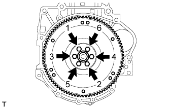
Install the flywheel sub-assembly with the 6 bolts in the order shown in the illustration.
- Torque:
- 78 N*m { 800 kgf*cm, 58 ft.*lbf }
-
-
INSTALL CLUTCH DISC ASSEMBLY (for Manual Transaxle)
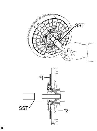
Text in Illustration *1 Clutch disc *2 Flywheel
-
Insert SST into the clutch disc assembly, and then insert them both into the flywheel sub-assembly.
- SST
- 09301-00210
Note
Insert the clutch disc assembly in the correct direction.
-
-
INSTALL CLUTCH COVER ASSEMBLY (for Manual Transaxle)
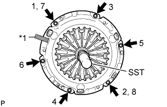
Text in Illustration *1 Matchmark
-
Align the matchmark on the clutch cover assembly with that on the flywheel sub-assembly.
-
Following the procedures shown in the illustration, tighten the 6 bolts in order, starting with the bolt located near the knock pin at the top.
- SST
- 09301-00210
- Torque:
- 19 N*m { 195 kgf*cm, 14 ft.*lbf }
Tech Tips
-
Following the order in the illustration, tighten the bolts evenly one at a time.
-
Move SST up and down, right and left lightly after checking that the disc is in the center, and tighten the bolts.
-
-
INSPECT AND ADJUST CLUTCH COVER ASSEMBLY (for Manual Transaxle)
-
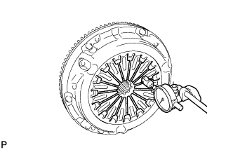
Using a dial indicator with a roller instrument, check the diaphragm spring tip alignment.
Maximum non-alignment 0.5 mm (0.020 in.) -
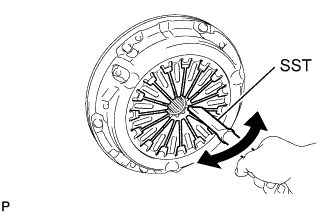
If the alignment is not as specified, using SST, adjust the diaphragm spring tip alignment.
- SST
- 09333-00013
-
-
INSTALL CLUTCH RELEASE WITH BEARING CYLINDER ASSEMBLY (for Manual Transaxle)
-
Clean and degrease all installation surfaces for the clutch release with bearing cylinder assembly.
-
Temporarily tighten the bleeder clutch release tube onto the clutch release with bearing cylinder assembly.
-
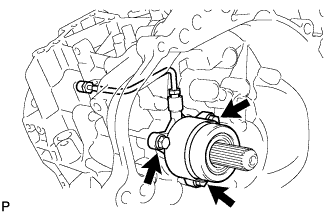
Install the new clutch release with the bearing cylinder with the 3 new bolts.
Note
-
The clutch release with bearing cylinder assembly and installation bolts cannot be reused and must be replaced with new ones.
-
Clean and degrease all installation surfaces and make sure the clutch release with bearing cylinder assembly fits securely with the transaxle during installation. The first bolt should be tightened by hand the clutch release with bearing cylinder assembly.
-
Ensure that none of the clutch disc spline grease adheres to the clutch release with bearing cylinder assembly.
-
The clutch release with bearing cylinder assembly cannot be disassembled.
- Torque:
- 23 N*m { 229 kgf*cm, 17 ft.*lbf }
-
-
Install the clutch tube boot onto the transaxle.
-
Install the release cylinder bleeder plug onto the clutch release bleeder.
- Torque:
- 8.4 N*m { 86 kgf*cm, 74 in.*lbf }
-
Install the release cylinder bleeder plug cap.
-
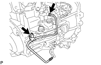
Text in Illustration *1 Bleeder clutch release tube *2 Clutch release bleeder Temporarily tighten the bleeder clutch release tube onto the clutch release bleeder.
-
Temporarily tighten the 2 bolts and install the clutch release bleeder.
-
Using a union nut wrench 10 mm, install the bleeder clutch release tube.
- Torque:
- 15 N*m { 155 kgf*cm, 11 ft.*lbf }
Note
Use the formula to calculate special torque values for situations when union nut wrench is combined with a torque wrench Click here.
-
-
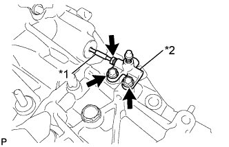
INSTALL CLUTCH RELEASE BLEEDER SUB-ASSEMBLY (for Manual Transaxle)
-
Text in Illustration *1 Bleeder clutch release tube *2 Clutch release bleeder Temporarily tighten the bleeder clutch release tube onto the clutch release bleeder.
-
Install the 2 bolts and clutch release bleeder.
- Torque:
- 17 N*m { 170 kgf*cm, 12 ft.*lbf }
-
Using a union nut wrench 10 mm, install the bleeder clutch release tube.
- Torque:
- 15 N*m { 155 kgf*cm, 11 ft.*lbf }
Note
Use the formula to calculate special torque values for situations when union nut wrench is combined with a torque wrench Click here.
-
-
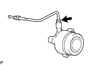
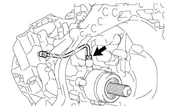
INSPECT CLUTCH PIPE LINE (for Manual Transaxle)
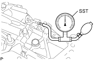
-
Using SST, apply pressure of 0.1 MPa to the clutch pipe location shown in the illustration and confirm that pressure is maintained for 15 seconds or more.
- SST
- 09992-00242
If the pressure drops, replace the bleeder clutch release tube.
-
-
INSTALL CLUTCH RELEASE BLEEDER SUB-ASSEMBLY (for Manual Transaxle)
-
Text in Illustration *1 Bleeder clutch release tube *2 Clutch release bleeder Temporarily tighten the bleeder clutch release tube onto the clutch release bleeder.
-
Install the 2 bolts and clutch release bleeder.
- Torque:
- 17 N*m { 170 kgf*cm, 12 ft.*lbf }
-
Using a union nut wrench 10 mm, install the bleeder clutch release tube.
- Torque:
- 15 N*m { 155 kgf*cm, 11 ft.*lbf }
Note
Use the formula to calculate special torque values for situations when union nut wrench is combined with a torque wrench Click here.
-
-
INSTALL BLEEDER TO ACCUMULATOR TUBE (for Manual Transaxle)
-
Install the bleeder clutch release tube with the bolt.
- Torque:
- 12 N*m { 122 kgf*cm, 9 ft.*lbf }
-
Using a union nut wrench 10 mm, install the bleeder clutch release tube.
- Torque:
- 15 N*m { 155 kgf*cm, 11 ft.*lbf }
Note
Use the formula to calculate special torque values for situations when union nut wrench is combined with a torque wrench Click here.
-
-
INSTALL MANUAL TRANSAXLE ASSEMBLY (for Manual Transaxle)
-
Make sure that the knock pins are not loose, bent, damaged or scratched and then install the transaxle onto the engine with the contact surfaces of the engine and transaxle flat against each other.
-
Align the input shaft with the clutch disc and install the manual transaxle onto the engine.
-
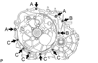
Install the 10 bolts.
- Torque:
- Bolt A
- 64 N*m { 653 kgf*cm, 47 ft.*lbf }
- Bolt B
- 37 N*m { 377 kgf*cm, 27 ft.*lbf, (for Flange Bolt) }
- 33 N*m { 337 kgf*cm, 24 ft.*lbf, (for Bolt with Washer) }
- Bolt C
- 39 N*m { 398 kgf*cm, 29 ft.*lbf }
Note
Insert knock pins into the knock pin holes securely so that the end face of the transaxle assembly fits close against the engine assembly before tightening the bolts.
-
-
INSTALL EXHAUST MANIFOLD
-
Place the 2 new gaskets and install the exhaust manifold, tightening the nuts and bolts in the sequence shown in the illustration.
- Torque:
- 28 N*m { 286 kgf*cm, 21 ft.*lbf }
-
-
INSTALL NO. 1 EXHAUST MANIFOLD HEAT INSULATOR
-
Install the No. 1 exhaust manifold heat insulator, tightening the nuts and bolts in the sequence shown in the illustration.
- Torque:
- 8.5 N*m { 87 kgf*cm, 75 in.*lbf }
-
-
INSTALL AIR FUEL RATIO SENSOR
-
Using SST, install the air fuel ratio sensor to the exhaust manifold.
- SST
- 09224-00010
- Torque:
- without SST
- 44 N*m { 449 kgf*cm, 32 ft.*lbf }
- with SST
- 40 N*m { 408 kgf*cm, 30 ft.*lbf }
Note
-
The "with SST" torque value is effective when using SST with a fulcrum length of 30 mm (1.18 in.).
-
The "with SST" torque value is effective when using a torque wrench with a fulcrum length of 300 mm (11.81 in.) Click here.
-
This torque value is effective when SST is parallel to the torque wrench.
-
Install the wire harness clamp and connect the air fuel ratio sensor connector.
-
-
INSTALL MANIFOLD STAY
-
After temporarily tightening the manifold stay until the nut is firm against the exhaust manifold, fully tighten the manifold stay to the block with the 2 bolts and then fully tighten the nut on the exhaust manifold side.
- Torque:
- 24 N*m { 245 kgf*cm, 18 ft.*lbf }
-
-
INSTALL ENGINE ASSEMBLY WITH TRANSAXLE
-
Install the engine assembly with transaxle Click here.
-