OIL PUMP REMOVAL

-
REMOVE ENGINE ASSEMBLY WITH TRANSAXLE
-
Remove the engine assembly with transaxle Click here.
-
-
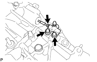
REMOVE STARTER ASSEMBLY
-
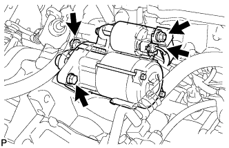
Open the terminal cap.
-
Remove the nut and disconnect the terminal 30.
-
Disconnect the connector.
-
Remove the 2 bolts and the starter assembly.
-
-
REMOVE DRIVE PLATE AND TORQUE CONVERTER CLUTCH SETTING BOLT (for CVT)
-
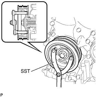
Use SST to hold the crankshaft pulley in place.
- SST
- 09960-10010 ( 09962-01000, 09963-01000 )
-
Remove the 6 drive plate and torque converter setting bolts.
-
-
REMOVE MANIFOLD STAY
-
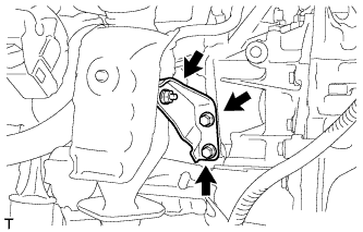
Remove the 2 bolts, the nut and the manifold stay.
-
-
REMOVE AIR FUEL RATIO SENSOR
-
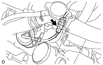
Disconnect the wire harness clamp and air fuel ratio sensor connector.
-
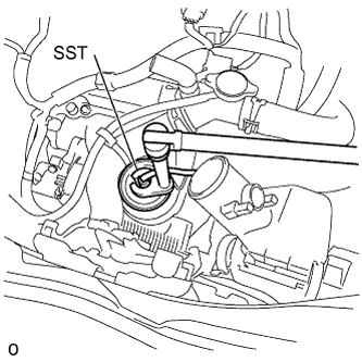
Using SST, remove the air fuel ratio sensor from the exhaust manifold.
- SST
- 09224-00010
-
-
REMOVE NO. 1 EXHAUST MANIFOLD HEAT INSULATOR
-
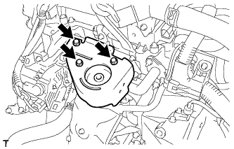
Remove the 3 bolts and the No. 1 exhaust manifold heat insulator.
-
-
REMOVE EXHAUST MANIFOLD
-
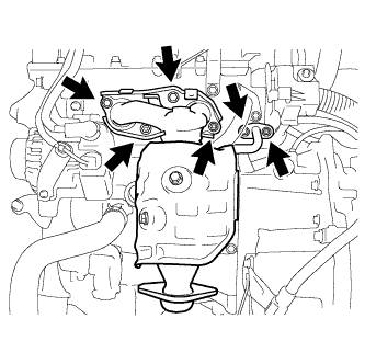
Remove the 2 bolts, the 4 nuts and the exhaust manifold.
-
Remove the 2 gaskets from the cylinder head.
-
-
REMOVE CONTINUOUSLY VARIABLE TRANSAXLE ASSEMBLY (for CVT)
-
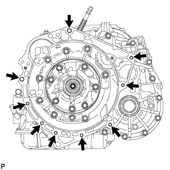
Remove the 9 bolts and the CVT.
Note
Do not twist the CVT when removing it from the engine, because the knock pins could be damaged.
-
-
REMOVE DRIVE PLATE AND RING GEAR SUB-ASSEMBLY (for CVT)
-
Using SST, hold the crankshaft.
- SST
- 09960-10010 ( 09962-01000, 09963-01000 )
-
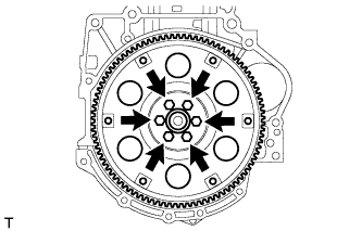
Remove the 6 bolts and the rear spacer, drive plate and the front spacer.
-
-
REMOVE MANUAL TRANSAXLE ASSEMBLY (for Manual Transaxle)
-
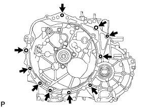
Remove the 8 bolts and the manual transaxle.
-
-
REMOVE BLEEDER TO ACCUMULATOR TUBE (for Manual Transaxle)
-
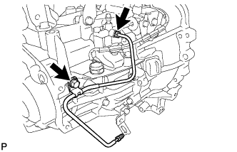
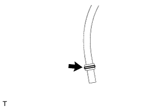
Using a union nut wrench 10 mm, separate the bleeder clutch release tube.
-
Remove the bolt and bleeder clutch release tube.
-
-
REMOVE CLUTCH RELEASE BLEEDER SUB-ASSEMBLY (for Manual Transaxle)
-
Using a union nut wrench 10 mm, separate the clutch release bleeder from the bleeder clutch release tube.
-
Remove the 2 bolts and clutch release bleeder.
-
-
REMOVE CLUTCH TUBE BOOT (for Manual Transaxle)
-
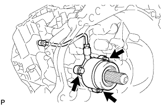
REMOVE CLUTCH RELEASE WITH BEARING CYLINDER ASSEMBLY (for Manual Transaxle)
-
Remove the 3 bolts and the clutch release with bearing cylinder assembly together with the bleeder clutch release tube.
-
-
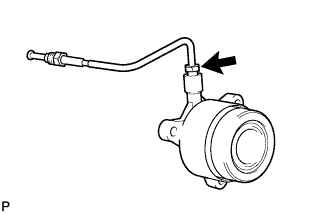
REMOVE BLEEDER CLUTCH RELEASE TUBE (for Manual Transaxle)
-
Using a union nut wrench 10 mm, separate the clutch release tube from the clutch release with bearing cylinder assembly.
-
-
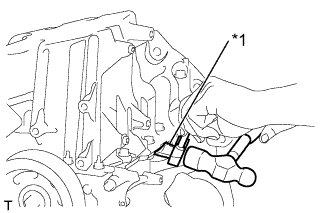
REMOVE CLUTCH COVER ASSEMBLY (for Manual Transaxle)
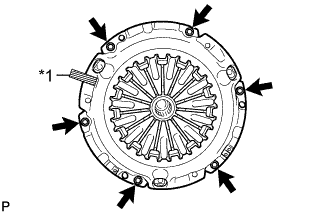
Text in Illustration *1 Matchmark
-
Put the matchmarks on the clutch cover and the flywheel.
-
Loosen each set bolt one turn at a time until the spring tension is released.
-
Remove the set bolts and pull off the clutch cover.
Note
Do not drop the clutch disc.
-
-
REMOVE CLUTCH DISC ASSEMBLY (for Manual Transaxle)
-
REMOVE FLYWHEEL SUB-ASSEMBLY (for Manual Transaxle)
-
Using SST, hold the crankshaft.
- SST
- 09960-10010 ( 09962-01000, 09963-01000 )
-
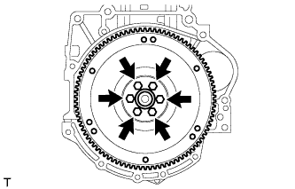
Remove the 6 bolts and the flywheel sub-assembly.
-
-
REMOVE GENERATOR ASSEMBLY
-
Remove the terminal cap.
-
Disconnect the connector and 2 harness clamps.
-
Remove the nut and terminal B.
-
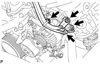
Remove the 2 bolts and 2 brackets.
-
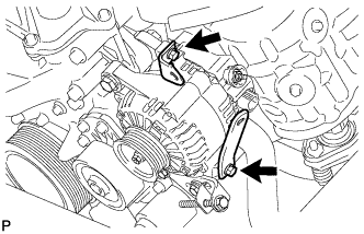
Remove the 2 bolts and fan belt adjusting bar.
-
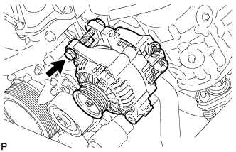
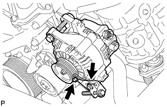
Remove the bolt and generator assembly.
-
-
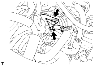
REMOVE THROTTLE WITH MOTOR BODY ASSEMBLY
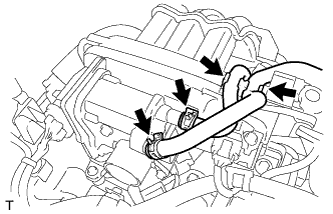
-
Separate the 2 water by-pass hoses from the hose clamp.
-
Disconnect the 2 water by-pass hoses.
-
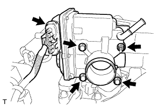
Disconnect the throttle with motor body assembly connector.
-
Remove the 3 bolts, the nut and the throttle with motor body assembly.
-
Remove the gasket from the intake manifold.
-
-
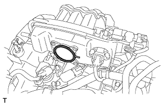
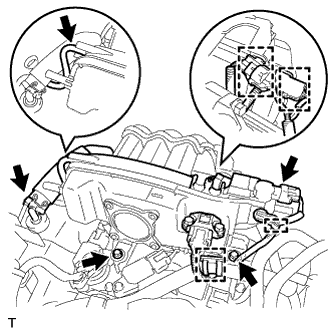
REMOVE INTAKE MANIFOLD
-
Disconnect the 2 connectors and 4 harness clamps from the intake manifold.
-
Disconnect the vacuum hose and ventilation hose and remove the 2 bolts from the intake manifold.
-
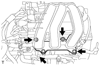
Remove the 2 bolts, 2 nuts and the intake manifold.
-
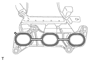
Remove the gasket from the intake manifold.
-
-
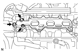
REMOVE NO. 1 INTAKE MANIFOLD INSULATOR
-
Remove the nut, the 2 bolts and the intake manifold insulator.
-
Remove the gasket from the cylinder head.
-
-
REMOVE EGR VALVE ASSEMBLY
-
Disconnect the EGR valve connector.
-
Separate the water by-pass hose.
-
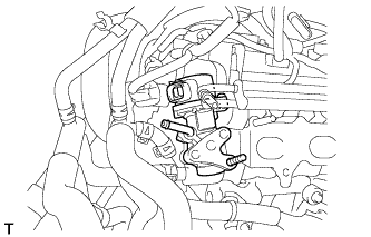
Rotate the EGR valve to avoid contact with the delivery pipe, and remove the EGR valve.
-
Remove the gasket.
-
-
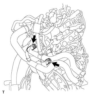
REMOVE WATER BY-PASS HOSE ASSEMBLY
-
Loosen the 2 clips and remove the water by-pass hose assembly.
-
-
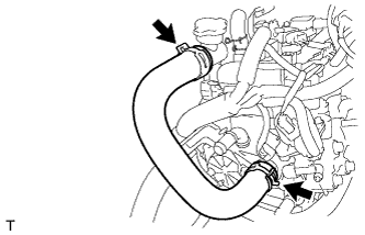
REMOVE NO. 1 RADIATOR HOSE
-
Loosen the 2 clips and remove the No. 1 radiator hose.
-
-
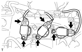
REMOVE NO. 1 IGNITION COIL
-
Disconnect the 3 No. 1 ignition coil connectors.
-
Remove the 3 bolts and the 3 No. 1 ignition coils.
-
-
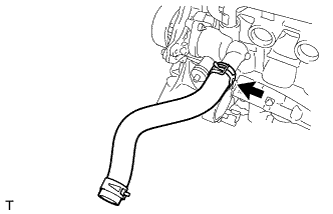
REMOVE NO. 2 RADIATOR HOSE
-
Loosen the clip and remove the No. 2 radiator hose.
-
-
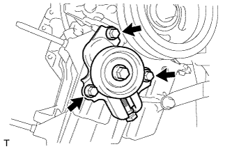
REMOVE IDLER PULLEY
-
Remove the 3 bolts and the idler pulley.
-
-
REMOVE OIL LEVEL DIPSTICK SUB-ASSEMBLY
-
REMOVE OIL LEVEL DIPSTICK GUIDE SUB-ASSEMBLY
-
Remove the bolt and the oil level dipstick guide sub-assembly.
-
Remove the O-ring from the oil level dipstick guide sub-assembly.
-
-
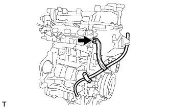
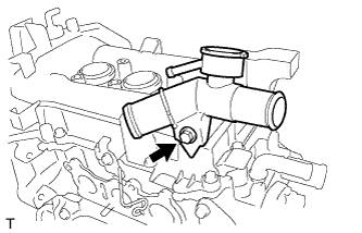
REMOVE WATER FILLER ASSEMBLY
-
Remove the bolt and the water filler assembly.
-
-
REMOVE WIRE HARNESS CLAMP BRACKET
-
Remove the bolt and the wiring harness clamp bracket.
-
-
REMOVE DRIVE SHAFT BEARING BRACKET
-
Remove the 2 bolts and the drive shaft bearing bracket.
-
-
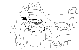
REMOVE OIL FILLER CAP SUB-ASSEMBLY
-
Remove the oil filler cap sub-assembly.
-
-
REMOVE CYLINDER HEAD COVER SUB-ASSEMBLY
-
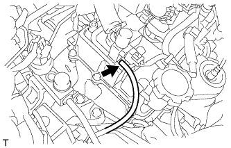
Disconnect the vacuum hose from the vacuum switching valve.
-
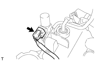
Disconnect the vacuum switching valve connector.
-
Separate the wire harness from the cylinder head cover sub-assembly
-
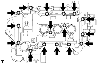
Remove the 16 bolts and the cylinder head cover sub-assembly.
-
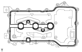
Remove the gasket from the cylinder head cover sub-assembly.
-
-
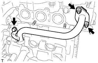
REMOVE NO. 1 WATER BY-PASS PIPE
-
Remove the bolt, the 2 nuts and the No. 1 water by-pass pipe.
-
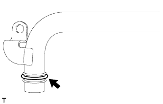
Remove the gasket from the No. 1 water by-pass pipe.
-
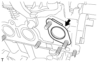
Remove the gasket from the cylinder head.
-
-
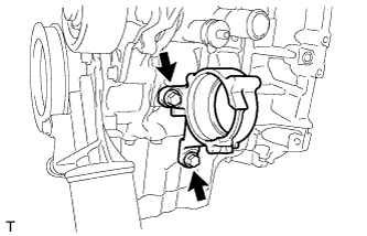
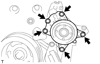
REMOVE WATER PUMP ASSEMBLY
-
Remove the 5 bolts and the water pump assembly.
-
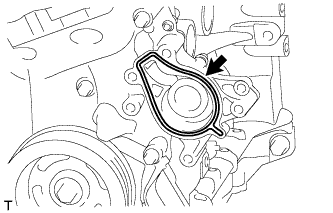
Remove the gasket.
-
-
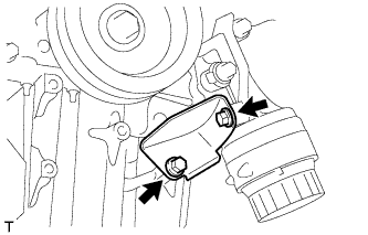
REMOVE OIL FILTER BRACKET STAY
-
Remove the 2 bolts and the oil filter bracket stay.
-
-
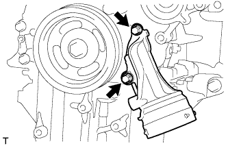
REMOVE OIL FILTER BRACKET
-
Remove the 2 bolts and the oil filter bracket.
-
Remove the gasket.
-
-
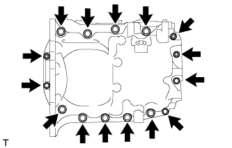
REMOVE OIL PAN SUB-ASSEMBLY
-
Remove the 12 bolts and 3 nuts.
-
Text in Illustration *1 Oil Pan Seal Cutter Using an oil pan seal cutter, remove the oil pan.
Note
Be careful not to damage the contact surfaces of the oil pan.
-
-
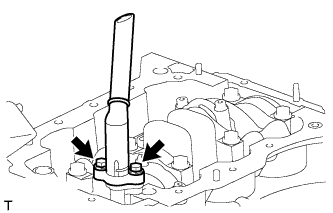
REMOVE OIL STRAINER SUB-ASSEMBLY
-
Remove the 2 bolts and oil strainer.
-
Remove the gasket.
-
-
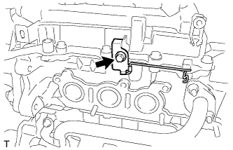
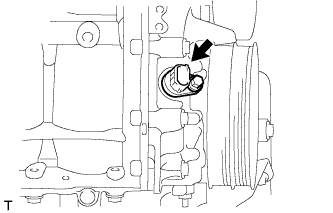
REMOVE CAMSHAFT TIMING OIL CONTROL VALVE ASSEMBLY
-
Disconnect the camshaft timing oil control valve assembly connector.
-
Remove the bolt and the camshaft timing oil control valve assembly.
-
-
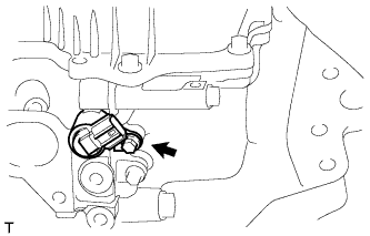
REMOVE CRANK POSITION SENSOR
-
Disconnect the crank position sensor connector.
-
Remove the bolt and the crank position sensor.
-
-
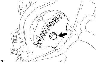
REMOVE CRANKSHAFT PULLEY
-
Operate the jack and slowly lower the engine.
Note
Do not lower the engine more than necessary.
-
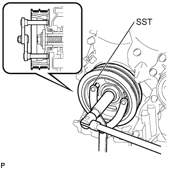
Using SST, hold the pulley in place and loosen the pulley bolt.
- SST
- 09960-10010 ( 09962-01000, 09963-01000 )
-
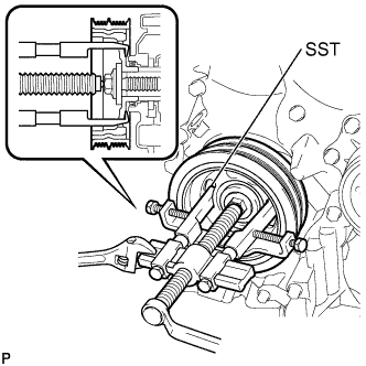
Using SST, remove the crankshaft pulley and pulley bolt.
- SST
- 09950-40011 ( 09951-04010, 09953-04030, 09958-04011, 09955-04011, 09954-04010, 09952-04010 )
-
-
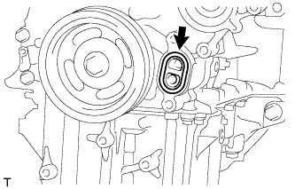
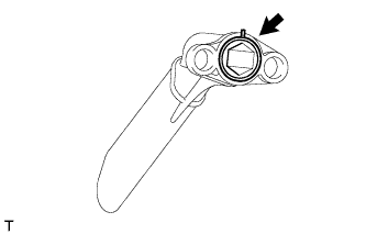
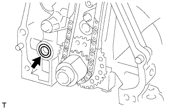
REMOVE TIMING GEAR COVER TIGHT PLUG
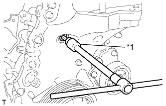
Text in Illustration *1 8 mm Socket Hexagon Wrench
-
Using an 8 mm socket hexagon wrench, remove the timing gear cover tight plug.
-
-
REMOVE TIMING CHAIN OR BELT COVER SUB-ASSEMBLY
-
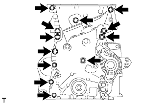
Remove the 12 bolts.
-
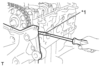
Text in Illustration *1 Protective Tape Using a screwdriver with its tip wrapped in protective tape, remove the timing chain cover by prying between the timing cover and cylinder head or cylinder block.
Note
Do not damage the contact surfaces of the cylinder head, cylinder block and timing chain cover.
-
Remove the gasket.
-
-
REMOVE STUD BOLT
-
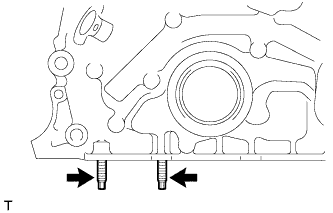
Remove the 2 stud bolts.
-
-
REMOVE VENTILATION CASE SUB-ASSEMBLY
-
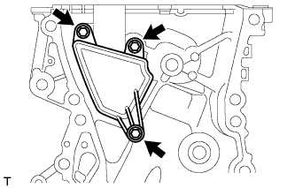
Remove the 3 bolts and the ventilation case sub-assembly.
-
-
REMOVE TIMING CHAIN OR BELT COVER OIL SEAL
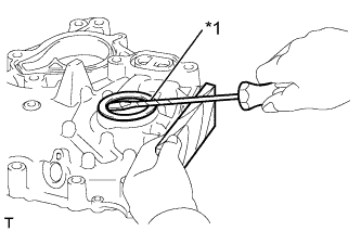
Text in Illustration *1 Protective Tape
-
Using a screwdriver with its tip wrapped in protective tape, pry out the oil seal.
-