STARTER (for 1.0 kW Type) REASSEMBLY

-
INSTALL STARTER CLUTCH SUB-ASSEMBLY
-
Apply high temperature grease to the bushing and spline of the starter clutch and stop collar.
-
Place the starter clutch and stop collar on the planet carrier shaft.
-
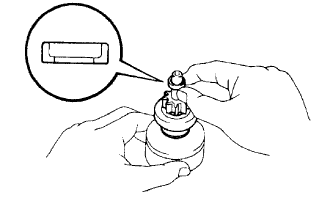
Apply high temperature grease to a new snap ring and install it to the planet carrier shaft groove.
-
Using a vise, compress the snap ring.
-
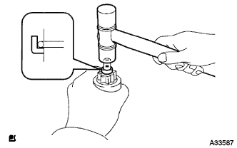
Hold the starter clutch, tap the planet carrier shaft, and install the starter pinion stop collar onto the snap ring with a plastic-faced hammer.
-
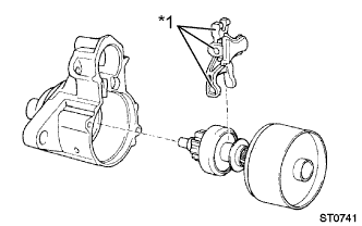
Text in Illustration *1 High-temperature grease Apply high temperature grease to the drive lever which is in contact with the starter pivot part of the drive lever.
-
Install the drive lever to the starter clutch.
-
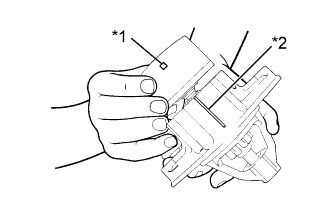
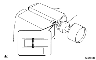
Text in Illustration *1 Alignment mark *2 Cutout Install the shock absorber by matching the drive housing cutout with the shock absorber alignment mark.
-
-
INSTALL STARTER ARMATURE ASSEMBLY
-
Install the starter armature to the starter yoke.
-
-
INSTALL STARTER BRUSH HOLDER ASSEMBLY
-
Install the brush holder.
-
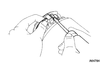
Using a screwdriver, hold the brush spring back and connect the brush into the brush holder. Connect the 4 brushes.
-
Apply turbine oil to the bearing of the end frame.
-
-
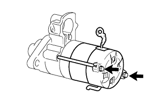
INSTALL STARTER COMMUTATOR END FRAME ASSEMBLY
-
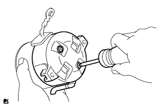
Install the end frame with the 2 screws.
- Torque:
- 1.5 N*m { 15 kgf*cm, 13 in.*lbf }
Note
To avoid interference between the brush holder and the dust starter protector, tilt the commutator end frame while installing it.
-
-
INSTALL STARTER YOKE ASSEMBLY
-
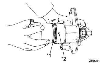
Text in Illustration *1 Cutout *2 Projection Align the cutout of the starter yoke with the projection of the planet carrier shaft sub-assembly.
-
Install the starter yoke with the 2 through bolts.
- Torque:
- 5.9 N*m { 60 kgf*cm, 52 in.*lbf }
-
-
INSTALL MAGNET STARTER SWITCH ASSEMBLY
-
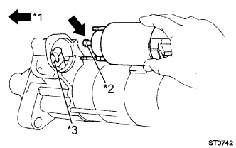
Text in Illustration *1 High-temperature grease *2 Plunger *3 Pinion Drive Lever Apply high temperature grease to the starter magnet switch plunger.
-
Install the starter magnet switch by hanging the starter magnet switch plunger on the upper area of the pinion drive lever.
-
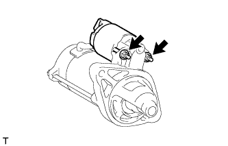
Install the magnet starter switch with the 2 nuts.
- Torque:
- 8.3 N*m { 85 kgf*cm, 74 in.*lbf }
-
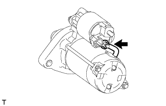
Connect the lead wire to the terminal with the nut.
- Torque:
- 9.8 N*m { 100 kgf*cm, 87 in.*lbf }
-