THERMOSTAT INSTALLATION

-
INSTALL THERMOSTAT
-
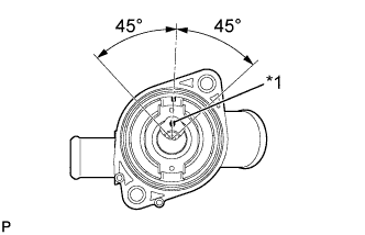
Text in Illustration *1 Jiggle valve Install the element to the water inlet as shown in the illustration.
Note
The jiggle valve may be set within 45° on either side of the prescribed position.
-
Install the spring to the water inlet.
-
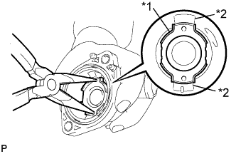
Text in Illustration *1 Frame *2 Protrusion Install the frame to the water inlet.
Tech Tips
Using needle nose pliers, push down on the frame to compress the spring. While the spring is compressed, turn the frame to engage it to the protrusions on the water inlet.
-
-
INSTALL NO. 2 WATER INLET HOUSING GASKET
-
Install a new gasket to the water inlet.
-
-
INSTALL WATER INLET
-
Install the water inlet with the 2 bolts.
- Torque:
- 10 N*m { 102 kgf*cm, 7 ft.*lbf }
-
-
CONNECT NO. 2 RADIATOR HOSE
-
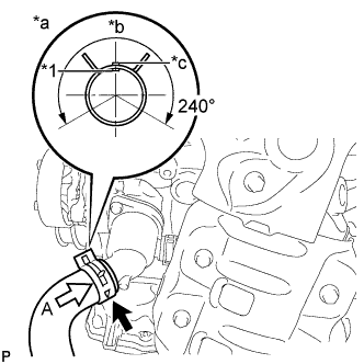
Text in Illustration *1 Yellow Paint Mark *a View A *b Upper Side *c Projection On Water Inlet Connect the No. 2 radiator hose to the water inlet.
Note
Perform the installation with the hose clip and mark at the correct angle.
-
-
CONNECT NO. 1 WATER BY-PASS PIPE
-
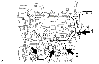
Connect the No. 1 water by-pass pipe to the water inlet.
-
Temporarily tighten the No. 1 water by-pass pipe with the 3 bolts.
-
Fully tighten the No. 1 water by-pass pipe with the 3 bolts in the order shown in the illustration.
- Torque:
- 22 N*m { 224 kgf*cm, 16 ft.*lbf }
-
-
INSTALL BEARING BRACKET HEAT INSULATOR
-
Install the bearing bracket heat insulator with the 2 bolts and 2 nuts.
- Torque:
- 16 N*m { 163 kgf*cm, 12 ft.*lbf }
-
-
INSTALL GENERATOR ASSEMBLY (for 80A Type)
-
Install the generator Click here.
-
-
INSTALL GENERATOR ASSEMBLY (for 100A Type)
-
Install the generator Click here.
-
-
ADD ENGINE COOLANT
-
Tighten the radiator drain cock plug.
-
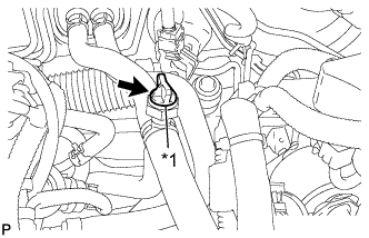
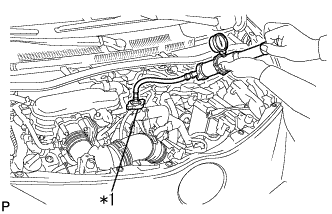
Text in Illustration *1 Air Bleed Valve Loosen the air bleed valve.
-
Remove the water filler cap sub-assembly.
-
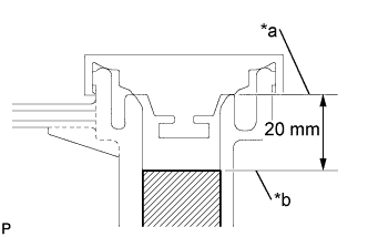
Text in Illustration *a Filler Tube End *b Coolant Level Slowly fill the radiator with TOYOTA Super Long Life Coolant (SLLC) from the water filler (Coolant level should be within 20 mm (0.787 in.) from the filler tube end).
Standard Capacity Item Capacity M/T 4.7 liters (5.0 US qts, 4.1 Imp. qts) CVT 4.9 liters (5.2 US qts, 4.3 Imp. qts) Note
Never use water as a substitute for engine coolant.
Tech Tips
TOYOTA vehicles are filled with TOYOTA SLLC at the factory. In order to avoid damage to the engine cooling system and other technical problems, only use TOYOTA SLLC or similar high quality ethylene glycol based non-silicate, non-amine, non-nitrite, non-borate coolant with long-life hybrid organic acid technology (coolant with long-life hybrid organic acid technology is a combination of low phosphates and organic acids).
-
Remove the reserve tank cap.
If the coolant level is low, add coolant.
-
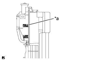
Text in Illustration *a FULL Line Fill the radiator reserve tank with coolant to the FULL line.
-
Text in Illustration *1 Air Bleed Valve Tighten the air bleed valve.
-
Install the water filler cap sub-assembly and reserve tank cap.
-
Start the engine and warm it up.
-
Bleed air from the cooling system.
Tech Tips
-
Before starting the engine, turn the A/C switch off.
-
Adjust the air conditioning temperature setting to MAX (HOT).
-
Adjust the air conditioning blower setting to LO.
-
Run the engine intermittently for 7 minutes or more (5 seconds running at 3000 rpm and 45 seconds idling, repeat several times).
-
-
Stop the engine, and wait until the engine coolant cools down.
-
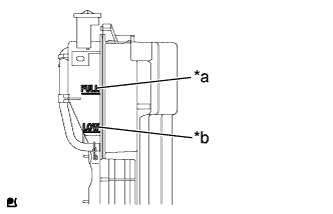
Text in Illustration *a FULL Line *b LOW Line After the engine is cooled down, check that the coolant level is between the FULL and LOW lines.
If the coolant level is low, add coolant to the reservoir tank FULL line.
-
-
INSPECT FOR COOLANT LEAK
CAUTION:
To avoid the danger of being burned, do not remove the water filler cap sub-assembly while the engine and radiator assembly are still hot. Thermal expansion will cause hot engine coolant and steam to blow out from the radiator assembly.
-
Text in Illustration *1 Radiator Cap Tester Fill the radiator assembly with engine coolant, and attach a radiator cap tester.
-
Pump the tester to 118 kPa (1.2 kgf/cm2, 17.1 psi), and then check that the pressure does not drop.
If the pressure drops, check the hoses, radiator assembly and water pump assembly for leaks. If there are no signs or traces of external engine coolant leaks, check the heater core, cylinder block and head.
-