EXHAUST MANIFOLD INSTALLATION

-
INSTALL NO. 3 EXHAUST MANIFOLD HEAT INSULATOR
-
Install the No. 3 exhaust manifold heat insulator with the 4 bolts.
- Torque:
- 10 N*m { 102 kgf*cm, 7 ft.*lbf }
-
-
INSTALL NO. 2 EXHAUST MANIFOLD HEAT INSULATOR
-
Install the No. 2 exhaust manifold heat insulator with the 3 bolts and the nut.
- Torque:
- 10 N*m { 102 kgf*cm, 7 ft.*lbf }
-
-
INSTALL EXHAUST MANIFOLD CONVERTER SUB-ASSEMBLY
-
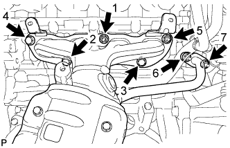
Place the new exhaust manifold to head gasket and new EGR inlet gasket, and install the exhaust manifold converter, tightening the 4 nuts and 3 bolts in the order shown in the illustration.
- Torque:
- 28 N*m { 286 kgf*cm, 21 ft.*lbf }
-
-
INSTALL MANIFOLD STAY
-
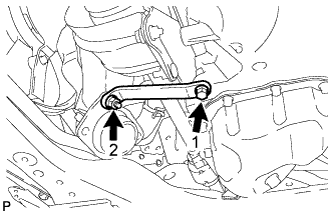
Temporarily tighten the manifold stay with the bolt and the nut.
-
Fully tighten the manifold stay with the bolt and nut in the order shown in the illustration.
- Torque:
- 28 N*m { 286 kgf*cm, 21 ft.*lbf }
-
-
INSTALL NO. 1 EXHAUST MANIFOLD HEAT INSULATOR
-
Install the No. 1 exhaust manifold heat insulator with the 2 nuts and the bolt.
- Torque:
- 10 N*m { 102 kgf*cm, 7 ft.*lbf }
-
-
INSTALL FRONT EXHAUST PIPE ASSEMBLY
-
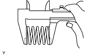
Using a vernier caliper, measure the free length of the compression springs.
Minimum Length Item Length Front 41.5 mm (1.634 in.) Tech Tips
If the length is not as specified, replace the compression spring.
-
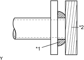
Text in Illustration *1 Gasket *2 Wooden Block Using a plastic hammer and a wooden block, tap in a new exhaust pipe gasket until its surface is flush with the exhaust manifold.
Note
-
Install the gasket in the correct direction.
-
Do not reuse the gasket.
-
Do not damage the gasket by dropping it, etc.
-
Do not damage the outer surface of the gasket.
-
Do not push in the gasket with the exhaust pipe when connecting it.
-
After the installation, check that the gaps between the flanges of the exhaust manifold and front exhaust pipe assembly are consistent front-to-rear and left-to-right.
-
-
Install the front exhaust pipe assembly to the exhaust manifold with the 2 bolts and the 2 compression springs.
- Torque:
- 43 N*m { 438 kgf*cm, 32 ft.*lbf }
-
Using a vernier caliper, measure the free length of the compression springs.
Minimum Length Item Length Rear 38.5 mm (1.594 in.) Tech Tips
If the length is not as specified, replace the compression spring.
-
Fully push a new exhaust pipe gasket onto the front exhaust pipe assembly.
Note
-
Install the gasket in the correct direction.
-
Do not reuse the gasket.
-
Do not damage the gasket by dropping it, etc.
-
Do not damage the outer surface of the gasket.
-
Do not push in the gasket with the exhaust pipe when connecting it.
-
After the installation, check that the gaps between the flanges of the exhaust manifold and front exhaust pipe assembly are consistent front-to-rear and left-to-right.
-
-
Install the front exhaust pipe assembly to the tail exhaust pipe assembly with the 2 bolts and the 2 compression springs.
- Torque:
- 43 N*m { 438 kgf*cm, 32 ft.*lbf }
-
-
INSTALL RADIATOR ASSEMBLY
-
Install the radiator assembly Click here.
-
-
INSTALL HEATED OXYGEN SENSOR
-
Install the heated oxygen sensor Click here.
-
-
INSTALL AIR FUEL RATIO SENSOR
-
Install the air fuel ratio sensor Click here.
-
-
INSPECT FOR EXHAUST GAS LEAK