INTAKE MANIFOLD INSTALLATION

-
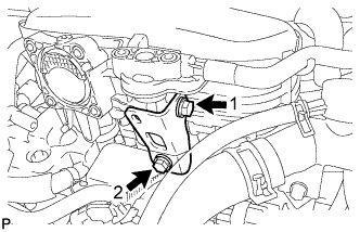
INSTALL HOSE CLAMP
-
Install the 2 hose clamps with the 2 bolts.
- Torque:
- 28 N*m { 286 kgf*cm, 21 ft.*lbf }
-
-
INSTALL WATER BY-PASS HOSE
-
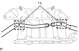
Text in Illustration *1 Blue Paint Mark Install the water by-pass hose to the hose clamp.
Tech Tips
Fix the areas with blue paint marks into the hose clamps.
-
-
INSTALL INTAKE MANIFOLD
-
Install a new No. 2 intake manifold to head gasket onto the cylinder head.
-
Install the EGR delivery chamber to the cylinder head.
-
Install a new manifold to cylinder head gasket onto the EGR delivery chamber.
-
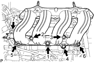
Install the intake manifold with the 5 bolts and 2 nuts in the order shown in the illustration.
- Torque:
- 28 N*m { 286 kgf*cm, 21 ft.*lbf }
-
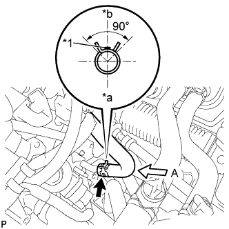
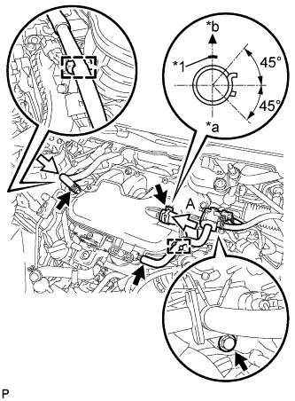
Text in Illustration *1 Yellow Paint Mark *a View A *b Upper Side Install the water by-pass hose to the EGR valve.
Note
Perform the installation with the hose clip at the correct angle.
-
-
INSTALL EGR PIPE CONNECTOR
-
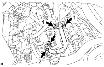
Install the 2 new EGR pipe gaskets.
-
Install the EGR pipe connector with the 4 nuts in the order shown in the illustration.
- Torque:
- 10 N*m { 102 kgf*cm, 7 ft.*lbf }
-
-
INSTALL UPPER INTAKE MANIFOLD SUB-ASSEMBLY
-
Install a new No. 1 intake manifold to head gasket onto the upper intake manifold sub-assembly.
-
Install the upper intake manifold sub-assembly with the 3 bolts and the 2 nuts.
- Torque:
- 28 N*m { 286 kgf*cm, 21 ft.*lbf }
-
Text in Illustration *1 White Paint Mark *a View A *b Upper Side Install the duty vacuum switching valve with the bolt.
- Torque:
- 8.8 N*m { 90 kgf*cm, 78 in.*lbf }
-
Install the water by-pass hose to the upper intake manifold sub-assembly.
-
Connect the fuel vapor feed hose and the union to connector tube hose.
-
Install the fuel vapor feed hose to the hose clamp.
-
Connect the ventilation hose.
Note
Perform the installation with the hose clips at the correct angle.
-
-
INSTALL INTAKE MANIFOLD STAY
-
Temporarily tighten the intake manifold stay with the 2 bolts.
-
Fully tighten the intake manifold stay with the 2 bolts in the order shown in the illustration.
- Torque:
- 28 N*m { 286 kgf*cm, 21 ft.*lbf }
-
-
INSTALL E. F. I VACUUM SENSOR ASSEMBLY
-
Install the E.F.I vacuum sensor assembly Click here.
-
-
INSTALL THROTTLE WITH MOTOR BODY ASSEMBLY
-
Install the throttle with motor body assembly Click here.
-
-
INSTALL WINDSHIELD WIPER MOTOR AND LINK
-
Install the windshield wiper motor and link Click here.
-