EXHAUST GAS TEMPERATURE SENSOR (for DPF) INSTALLATION

-
INSTALL EXHAUST GAS TEMPERATURE SENSOR
-
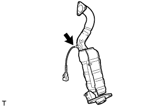
Using a union nut wrench (14 mm), install the exhaust gas temperature sensor.
- Torque:
- 30 N*m { 306 kgf*cm, 22 ft.*lbf }
Note
Use the formula to calculate special torque values for situations where a union nut wrench is combined with a torque wrench Click here.
-
-
INSTALL EXHAUST MANIFOLD CONVERTER SUB-ASSEMBLY
-
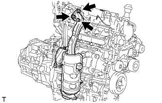
Install a new gasket onto the turbocharger.
-
Install the exhaust manifold converter with 3 new nuts.
- Torque:
- 26 N*m { 265 kgf*cm, 19 ft.*lbf }
-
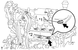
Text in Illustration *1 Stud Bolt *2 Nut Install the stud bolt and nut.
- Torque:
- Stud Bolt
- 22 N*m { 224 kgf*cm, 16 ft.*lbf }
- Nut
- 43 N*m { 438 kgf*cm, 32 ft.*lbf }
-
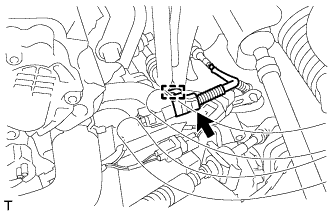
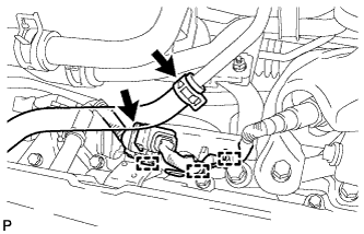
Engage the harness camp and connect the connector.
-
-
INSTALL NO. 1 AIR HOSE
-
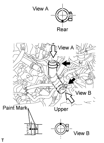
Install the No. 1 air hose with the 2 hose clamps.
Tech Tips
-
Align the paint mark of the intercooler air hose with the location mark of the turbocharger.
-
Align the paint mark of the intercooler air hose with the location mark of No. 1 air tube.
-
Make sure that the hose clamp is at the correct angle when installing.
-
-
-
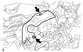
INSTALL MANIFOLD SUPPORT BRACKET
-
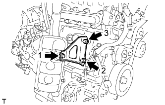
Temporarily tighten the manifold support bracket with the 2 bolts and nut.
-
Fully tighten the 2 bolts and nut, as shown in the illustration.
- Torque:
- 37 N*m { 377 kgf*cm, 27 ft.*lbf }
-
-
INSTALL NO. 2 MANIFOLD SUPPORT BRACKET
-
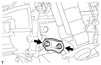
Install the No. 2 manifold support bracket with the bolt and nut.
- Torque:
- 37 N*m { 377 kgf*cm, 27 ft.*lbf }
-
-
INSTALL TAIL EXHAUST PIPE ASSEMBLY
-
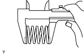
Using a vernier caliper, measure the free length of the compression spring.
Minimum length 41.5 mm (1.634 in.) If the length is not as specified, replace the compression spring.
-
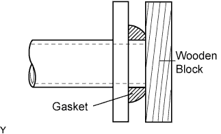
Using a plastic hammer and a wooden block, tap in a new gasket until its surface is flush with the exhaust manifold.
Note
-
Install the exhaust pipe gasket in the correct direction.
-
Do not damage the outer surface of the exhaust pipe gasket.
-
Do not reuse the exhaust pipe gasket.
-
Do not push in the gasket with the exhaust pipe when connecting it.
-
-
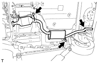
Hang the tail exhaust pipe assembly with the 3 No. 4 exhaust pipe supports.
-
Install the tail exhaust pipe assembly with the 2 compression springs and 2 bolts.
- Torque:
- 43 N*m { 438 kgf*cm, 32 ft.*lbf }
-
-
INSTALL TIE ROD END SUB-ASSEMBLY RH
Tech Tips
Use the same procedure for the RH side as for the LH side.
-
INSTALL FRONT WHEEL RH
-
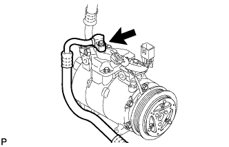
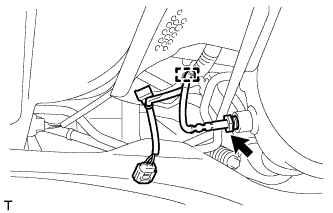
CONNECT SUCTION HOSE SUB-ASSEMBLY (w/ Air Conditioning System)
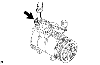
-
Remove the attached vinyl tape from the suction hose.
-
Sufficiently apply compressor oil to a new O-ring and the fitting surface of the cooler compressor.
Compressor oil ND-OIL 8 or equivalent -
Install the O-ring onto the suction hose.
-
Connect the suction hose to the cooler compressor with the bolt.
- Torque:
- 9.8 N*m { 100 kgf*cm, 87 in.*lbf }
-
-
CONNECT DISCHARGE HOSE SUB-ASSEMBLY (w/ Air Conditioning System)
-
Remove the attached vinyl tape from the discharge hose.
-
Sufficiently apply compressor oil to a new O-ring and the fitting surface of the cooler compressor.
Compressor oil ND-OIL 8 or equivalent -
Install the O-ring onto the discharge hose.
-
Connect the discharge hose to the cooler compressor with the bolt.
- Torque:
- 9.8 N*m { 100 kgf*cm, 87 in.*lbf }
-
-
INSTALL OIL LEVEL DIPSTICK GUIDE
-
Install the O-ring to the oil level dipstick guide.
-
Install the oil level dipstick guide with the 2 bolts.
- Torque:
- 9.0 N*m { 92 kgf*cm, 80 in.*lbf }
-
Engage the harness clamp and install the oil level dipstick guide and wire harness with the bolt.
- Torque:
- 9.0 N*m { 92 kgf*cm, 80 in.*lbf }
-
-
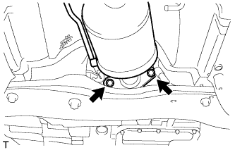
INSTALL NO. 2 TURBO INSULATOR
-
Install the No. 2 turbo insulator with the bolt and nut.
- Torque:
- 7.0 N*m { 71 kgf*cm, 62 ft.*lbf }
-
-
INSTALL AIR FUEL RATIO SENSOR
-
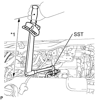
Text in Illustration *1 Fulcrum length Using SST, install the air fuel ratio sensor.
- SST
- 09224-00010
- Torque:
- without SST
- 44 N*m { 449 kgf*cm, 32 ft.*lbf }
- with SST
- 40 N*m { 408 kgf*cm, 30 ft.*lbf }
Note
-
The "with SST" torque value is effective when using a torque wrench with a fulcrum length of 300 mm (11.81 in.) Click here.
-
This torque value is effective when SST is parallel to the torque wrench.
-
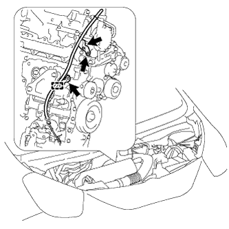
Engage the 3 wire harness clamps and install the air fuel ratio sensor wire harness.
-
Connect the air fuel ratio sensor connector.
-
-
INSTALL ENGINE COVER ASSEMBLY
-
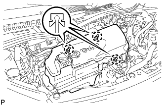
Engage the 3 claws and install the engine cover.
-
-
INSTALL AIR CLEANER HOSE ASSEMBLY
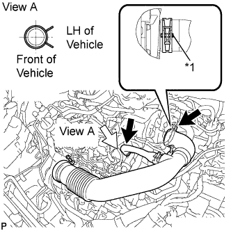
Text in Illustration *1 Paint Mark
-
Install the air cleaner hose.
Note
Position the clip so that the claws are centered over the paint mark on the hose.
-
-
INSTALL AIR CLEANER CASE SUB-ASSEMBLY
-
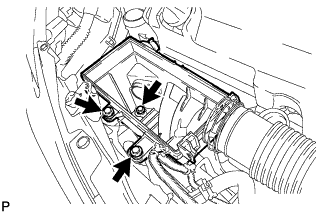
Install the air cleaner case with the 3 bolts.
- Torque:
- 7.5 N*m { 76 kgf*cm, 66 in.*lbf }
-
-
INSTALL AIR CLEANER FILTER ELEMENT SUB-ASSEMBLY
-
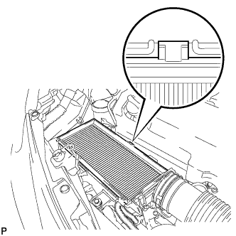
Install the air cleaner filter element.
Note
Engage the air cleaner filter element protrusion with the air cleaner case groove.
-
-
INSTALL AIR CLEANER CAP SUB-ASSEMBLY
-
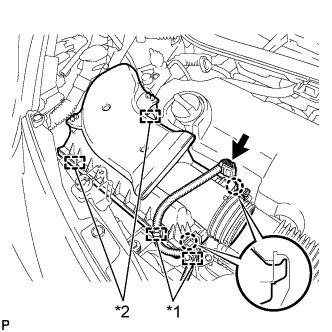
Engage the 2 claws and 2 clamps and install the air cleaner cap.
-
Connect the connector and 2 wire harness clamps.
Text in Illustration *1 Wire harness clamp *2 Clamp -
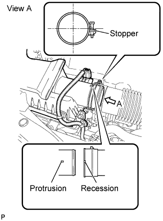
Connect the air cleaner hose to the air cleaner cap.
Tech Tips
-
The clamp should contact the air cleaner hose stopper.
-
Make sure that the air cleaner hose recession is securely engaged with the air cleaner cap protrusion.
-
-
-
INSTALL FRONT WIPER MOTOR AND LINK
-
Install the front wiper motor and link Click here.
-
-
INSTALL EXHAUST PIPE (w/ Combustion Type Power Heater)
-
Install the exhaust pipe Click here.
-
-
INSTALL NO. 2 EXHAUST GAS TEMPERATURE SENSOR
-
Using a union nut wrench (14 mm), install the No. 2 exhaust gas temperature sensor.
- Torque:
- 30 N*m { 306 kgf*cm, 22 ft.*lbf }
Note
Use the formula to calculate special torque values for situations where a union nut wrench is combined with a torque wrench Click here.
-
Engage the harness clamp.
-
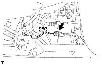
Engage the harness clamp and connect the No. 2 exhaust gas temperature sensor connector.
-
-
INSTALL ENGINE UNDER COVER
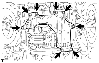
-
Install the engine under cover with the 4 bolts and 4 clips.
- Torque:
- 5.0 N*m { 51 kgf*cm, 44 in.*lbf }
-
-
CHARGE REFRIGERANT
-
WARM UP ENGINE
-
INSPECT FOR REFRIGERANT LEAK
-
INSPECT FOR EXHAUST GAS LEAK