EXHAUST GAS TEMPERATURE SENSOR (for DPF) REMOVAL

-
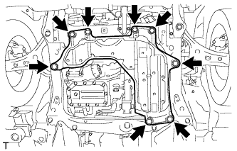
REMOVE ENGINE UNDER COVER
-
Remove the 4 bolts, 4 clips and the engine under cover.
-
-
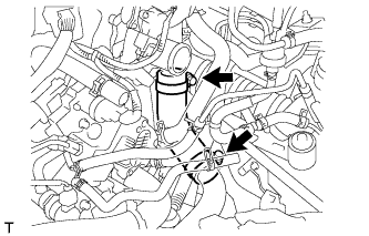
REMOVE NO. 2 EXHAUST GAS TEMPERATURE SENSOR
-
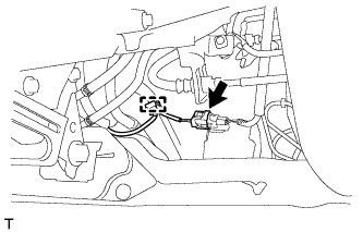
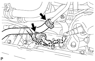
Disconnect the No. 2 exhaust gas temperature sensor connector and disengage the harness clamp.
-
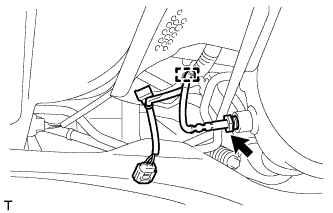
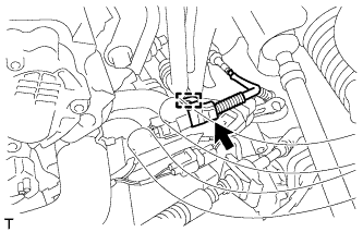
Disengage the harness clamp.
-
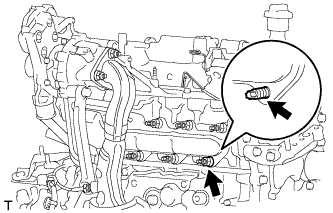
Using a union nut wrench (14 mm), remove the No. 2 exhaust gas temperature sensor.
-
-
REMOVE EXHAUST PIPE (w/ Combustion Type Power Heater)
-
Remove the exhaust pipe Click here.
-
-
REMOVE FRONT WIPER MOTOR AND LINK
-
Remove the front wiper motor and link Click here.
-
-
RECOVER REFRIGERANT FROM REFRIGERATION SYSTEM (w/ Air Conditioning System)
-
REMOVE AIR CLEANER CAP SUB-ASSEMBLY
-
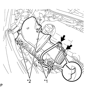
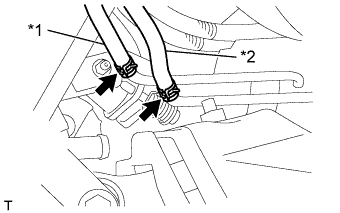
Text in Illustration *1 Wire harness clamp *2 Clamp Disconnect the connector and 2 wire harness clamps.
-
Loosen the hose clamp and separate the air cleaner hose.
-
Disengage the 2 clamps and 2 claws and remove the air cleaner cap.
-
-
REMOVE AIR CLEANER FILTER ELEMENT SUB-ASSEMBLY
-
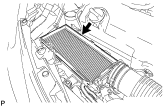
Remove the air cleaner filter element.
-
-
REMOVE AIR CLEANER CASE SUB-ASSEMBLY
-
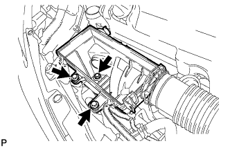
Remove the 3 bolts and the air cleaner case.
-
-
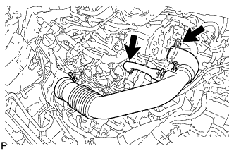
REMOVE AIR CLEANER HOSE ASSEMBLY
-
Remove the air cleaner hose.
-
-
REMOVE ENGINE COVER ASSEMBLY
-
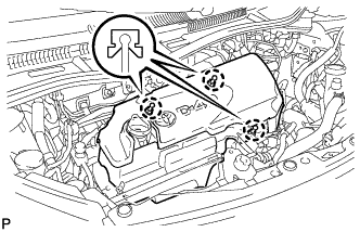
Disengage the 3 claws and remove the engine cover.
-
-
REMOVE AIR FUEL RATIO SENSOR
-
Disconnect the union to connector tube hose.
-
Disconnect the air fuel ratio sensor connector.
-
Disengage the 3 wire harness clamps and separate the air fuel ratio sensor wire harness.
-
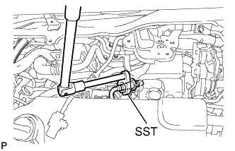
Using SST, remove the air fuel ratio sensor.
- SST
- 09224-00010
-
-
REMOVE NO. 2 TURBO INSULATOR
-
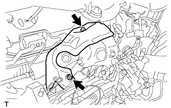
Remove the bolt, nut and No. 2 turbo insulator.
-
-
REMOVE OIL LEVEL DIPSTICK GUIDE
-
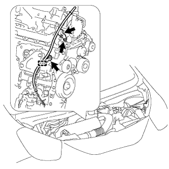
Remove the bolt, disengage the harness clamp and separate the wire harness.
-
Remove the 2 bolts and the oil level dipstick guide.
-
Remove the O-ring from the oil level dipstick guide.
-
-
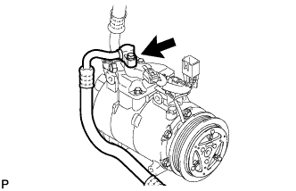
DISCONNECT DISCHARGE HOSE SUB-ASSEMBLY (w/ Air Conditioning System)
-
Remove the bolt and disconnect the discharge hose from the compressor.
-
Remove the O-ring from the discharge hose.
Note
Seal the openings of the disconnected parts using vinyl tape to prevent the entry of moisture and foreign matter.
-
-
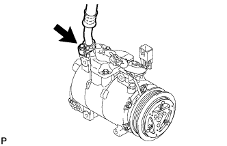
DISCONNECT SUCTION HOSE SUB-ASSEMBLY (w/ Air Conditioning System)
-
Remove the bolt and disconnect the suction hose from the compressor.
-
Remove the O-ring from the suction hose.
Note
Seal the openings of the disconnected parts using vinyl tape to prevent the entry of moisture and foreign matter.
-
-
REMOVE FRONT WHEEL RH
-
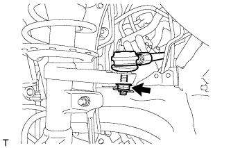
SEPARATE TIE ROD END SUB-ASSEMBLY RH
-
Remove the cotter pin and castle nut.
-
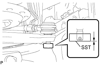
Install SST (spacer B) to the threaded section of the tie rod end.
- SST
- 09960-20010 ( 09961-02060 )
Note
Make sure the upper ends of the threaded section of the tie rod end and SST (spacer B) are aligned.
-
Using SST, separate the tie rod end from the front axle assembly.
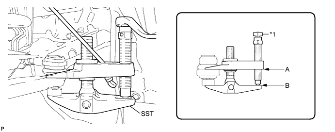
Text in Illustration *1 Place the wrench here - SST
- 09960-20010 ( 09961-02010 )
Note
-
Make sure to tie the string of SST to the vehicle to prevent SST from dropping.
-
Install SST so that A and B are parallel.
-
Be sure to place the wrench on the part indicated in the illustration.
-
Do not damage the ball joint dust cover.
-
Do not damage the front disc brake dust cover.
-
-
REMOVE TAIL EXHAUST PIPE ASSEMBLY
-
*1 No. 7 Air hose *2 No. 8 Air hose Disconnect the 2 air hoses.
-
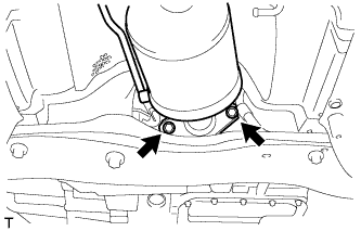
Remove the 2 bolts and 2 compression springs.
-
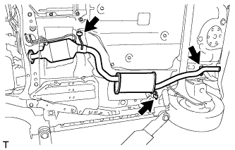
Remove the 3 No. 4 exhaust pipe supports and remove the tail exhaust pipe assembly.
-
-
REMOVE NO. 2 MANIFOLD SUPPORT BRACKET
-
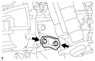
Remove the bolt, nut and No. 2 manifold support bracket.
-
-
REMOVE MANIFOLD SUPPORT BRACKET
-
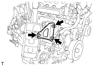
Remove the 2 bolts, nut and manifold support bracket.
-
-
REMOVE NO. 1 AIR HOSE
-
Loosen the 2 hose clamps and remove the No. 1 air hose.
-
-
REMOVE EXHAUST MANIFOLD CONVERTER SUB-ASSEMBLY
-
Disconnect the connector and disengage the harness clamp.
-
Remove the nut and stud bolt.
-
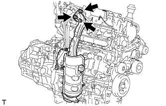
Remove the 3 nuts and exhaust manifold converter.
-
Remove the gasket from the turbocharger.
-
-
REMOVE EXHAUST GAS TEMPERATURE SENSOR
-
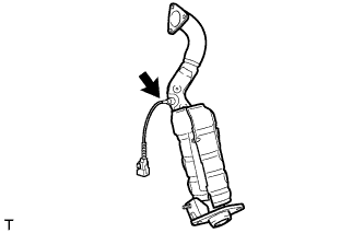
Using a union nut wrench (14 mm), remove the exhaust gas temperature sensor.
-