CANISTER REMOVAL

-
SEPARATE FUEL TANK WIRE
-
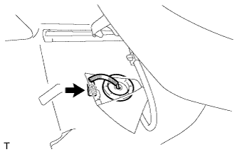
Peel back the floor carpet under the front left seat, disconnect the fuel tank wire connector, and pass the grommet through the floor.
-
-
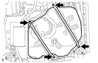
REMOVE NO. 1 FUEL TANK PROTECTOR SUB-ASSEMBLY
-
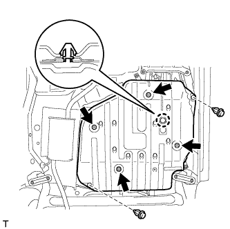
Remove the 2 clips and 4 nuts.
-
Disengage the claw and remove the No. 1 fuel tank protector.
-
-
SEPARATE NO. 1 CHARCOAL CANISTER OUTLET HOSE
-
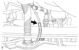
Separate the No. 1 charcoal canister outlet hose.
-
-
SEPARATE FUEL TANK FILLER PIPE SUB-ASSEMBLY
-
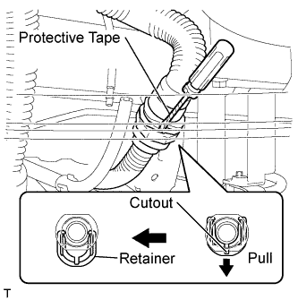
Insert a screwdriver with its tip wrapped in protective tape in the quick connector cutout as shown in the illustration, push the quick connector lock forward, and disconnect the breather tube.
Note
-
Check for dirt or other foreign matter on the parts to be disconnected and clean them if necessary.
-
The quick connector seals with an O-ring. Ensure that there is no damage or foreign matter on the contact surface.
-
Do not use any tools.
-
Do not bend or twist the tubes.
-
Protect the contact surface by covering it with a plastic bag.
-
If the connector is stuck, push and pull on the parts to separate them.
-
-
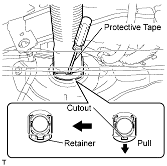
Insert a screwdriver with its tip wrapped in protective tape in the quick connector cutout as shown in the illustration, push the quick connector lock forward and disconnect the inlet tube.
Note
-
Check for dirt or other foreign matter on the parts to be disconnected and clean them if necessary.
-
The quick connector seals with an O-ring. Ensure that there is no damage or foreign matter on the contact surface.
-
Do not use any tools.
-
Do not bend or twist the tubes.
-
Protect the contact surface by covering it with a plastic bag.
-
If the connector is stuck, push and pull on the parts to separate them.
-
-
-
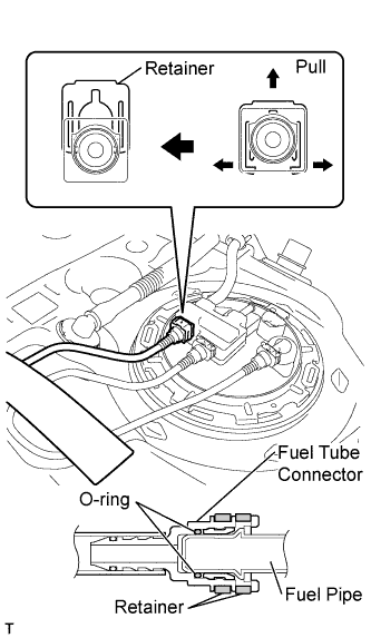
SEPARATE FUEL TANK MAIN TUBE SUB-ASSEMBLY
-
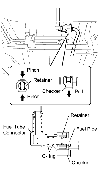
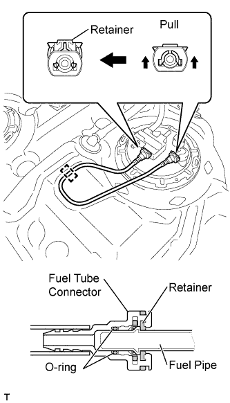
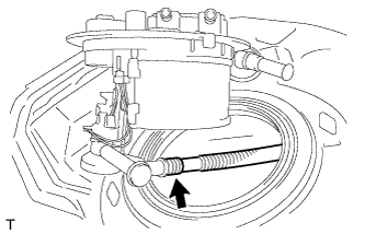
Release the checker as shown in the illustration.
-
Pinch the retainer to release it as shown in the illustration and separate the fuel tank main tube.
Note
-
Check for dirt or other foreign matter on the parts to be disconnected and clean them if necessary.
-
The quick connector seals with an O-ring. Ensure that there is no damage or foreign matter on the contact surface.
-
Do not use any tools.
-
Do not bend or twist the tubes.
-
Protect the contact surface by covering it with a plastic bag.
-
If the connector is stuck, push and pull on the parts to separate them.
-
-
-
SEPARATE REAR FUEL EMISSION TUBE SUB-ASSEMBLY
-
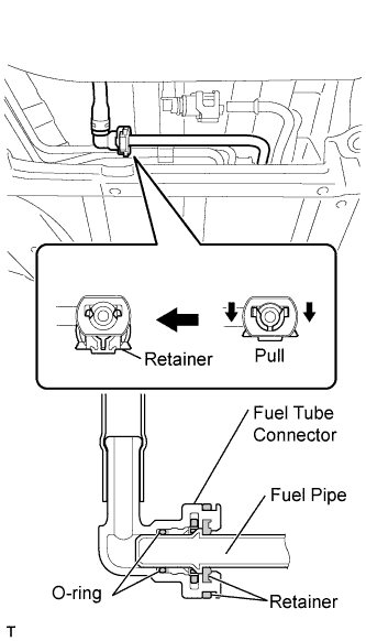
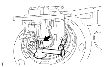
Release the retainer as shown in the illustration and separate the fuel emission tube.
Note
-
Check for dirt or other foreign matter on the parts to be disconnected and clean them if necessary.
-
The quick connector seals with an O-ring. Ensure that there is no damage or foreign matter on the contact surface.
-
Do not use any tools.
-
Do not bend or twist the tubes.
-
Protect the contact surface by covering it with a plastic bag.
-
If the connector is stuck, push and pull on the parts to separate them.
-
-
-
REMOVE FUEL TANK ASSEMBLY
-
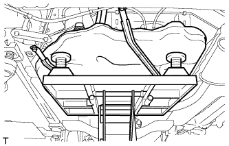
Using an engine lifter, support the fuel tank.
-
Remove the 4 bolts and the fuel tank.
Note
Make sure that the fuel tank does not fall.
-
-
SEPARATE FUEL TANK WIRE
-
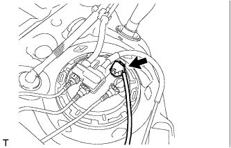
Disconnect the fuel tank wire connector from the fuel tank vent tube assembly.
-
-
SEPARATE REAR FUEL EMISSION TUBE SUB-ASSEMBLY
-
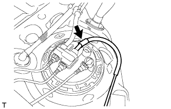
Separate the fuel emission tube from the fuel tank vent tube assembly.
-
-
SEPARATE NO. 1 FUEL EVAPORATION TUBE SUB-ASSEMBLY
-
Remove the No. 2 fuel tank cushion from the fuel tank.
-
Release the retainer as shown in the illustration and separate the No. 1 fuel evaporation tube from the fuel tank vent tube assembly.
Note
-
Check for dirt or other foreign matter on the parts to be disconnected and clean them if necessary.
-
The quick connector seals with an O-ring. Ensure that there is no damage or foreign matter on the contact surface.
-
Do not use any tools.
-
Do not bend or twist the tubes.
-
Protect the contact surface by covering it with a plastic bag.
-
If the connector is stuck, push and pull on the parts to separate them.
-
-
-
REMOVE NO. 2 FUEL EVAPORATION TUBE SUB-ASSEMBLY
-
Release the retainer as shown in the illustration and disconnect the No. 2 fuel evaporation tube from the fuel tank vent tube assembly.
Note
-
Check for dirt or other foreign matter on the parts to be disconnected and clean them if necessary.
-
The quick connector seals with an O-ring. Ensure that there is no damage or foreign matter on the contact surface.
-
Do not use any tools.
-
Do not bend or twist the tubes.
-
Protect the contact surface by covering it with a plastic bag.
-
If the connector is stuck, push and pull on the parts to separate them.
-
-
Disengage the clamp and remove the No. 2 fuel evaporation tube from the fuel tank.
-
-
REMOVE NO. 1 CHARCOAL CANISTER OUTLET HOSE
-
Separate the No. 1 charcoal canister outlet hose from the fuel tank vent tube assembly.
-
Disengage the clamp and remove the No. 1 charcoal canister outlet hose.
-
-
REMOVE FUEL PUMP GAUGE RETAINER
-
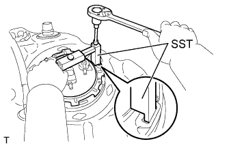
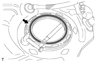
Using a 6 mm hexagon wrench, set SST on the fuel pump gauge retainer.
- SST
- 09808-14020 ( 09808-01410, 09808-01420, 09808-01430 )
Tech Tips
Align the ribs of the fuel pump gauge retainer with the tips of SST.
-
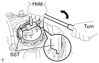
Using SST, loosen the fuel pump gauge retainer.
- SST
- 09808-14020 ( 09808-01410, 09808-01420, 09808-01430 )
Note
Do not use any tools other than SST.
Tech Tips
Align the ribs of the fuel pump gauge retainer with the tips of SST.
-
Remove the fuel pump gauge retainer while holding the fuel tank vent tube assembly by hand.
-
-
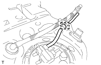
REMOVE FUEL TANK VENT TUBE ASSEMBLY
Note
Do not disconnect the tube shown in the illustration.
-
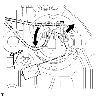
Text in Illustration *1 Arrows Rotate the fuel tank vent tube toward the inside of the tank and pull out the fuel tank vent tube assembly in the opposite direction of the arrow, which shows the fuel tank sender gauge insertion direction.
Note
Do not bend the sender gauge arm.
-
Disengage the 2 claws of the fuel tank vent tube, disconnect the fuel tank vent tube, and remove the fuel tank vent tube assembly.
-
-
REMOVE FUEL TANK SUCTION TUBE GASKET
-
Remove the gasket from the fuel tank.
-